
Apparatus for forming groove used in cutting blade

A technology for cutting blades and forming devices, applied in broaching devices, broaching knives, milling equipment, etc., can solve the problems that square grooves cannot be accurately formed, cannot be accurately fixed, and are not provided

Inactive Publication Date: 2005-07-13
朴 洪顺
View PDF0 Cites 6 Cited by
  • Summary
  • Abstract
  • Description
  • Claims
  • Application Information

AI Technical Summary

Problems solved by technology

[0013] In this device, when a grinding roller of a very small length corresponding to the width of the cutting blade is pressed against the upper and lower surfaces of the cutting blade, since there is no separate structure, so the machining area of ​​the cutting blade may be formed during machining, making it difficult to precisely form grooves on the cutting blade
[0014] In addition, in the case where the cutting blade is formed to have a T-shaped cross section, square grooves cannot be precisely formed at predetermined positions
Since it is difficult to grind one end of the cutting blade to have a semicircular cross-sectional shape, the cutting blade part cannot be precisely fixed on the cutting blade

Method used


Image

  • Apparatus for forming groove used in cutting blade
  • Apparatus for forming groove used in cutting blade
  • Apparatus for forming groove used in cutting blade

Examples


Embodiment Construction

[0033] Referring now to the drawings, in which like reference numerals designate like or similar parts throughout the different views.

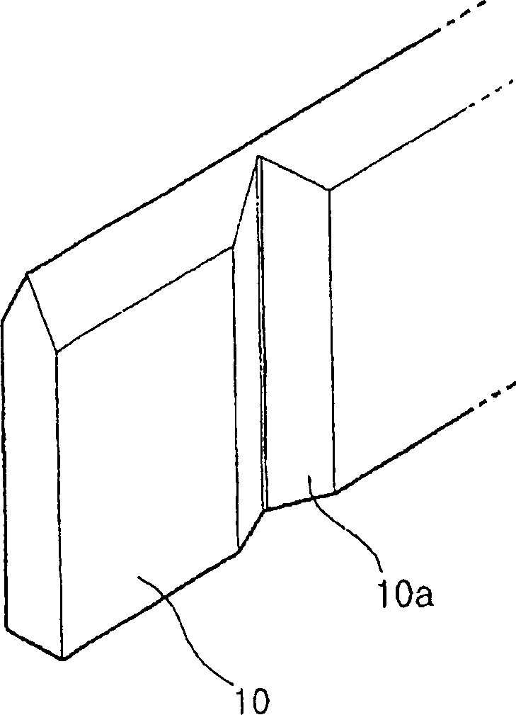
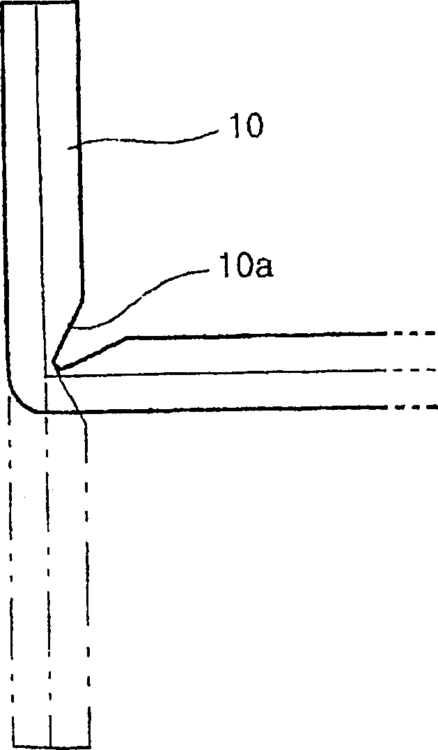
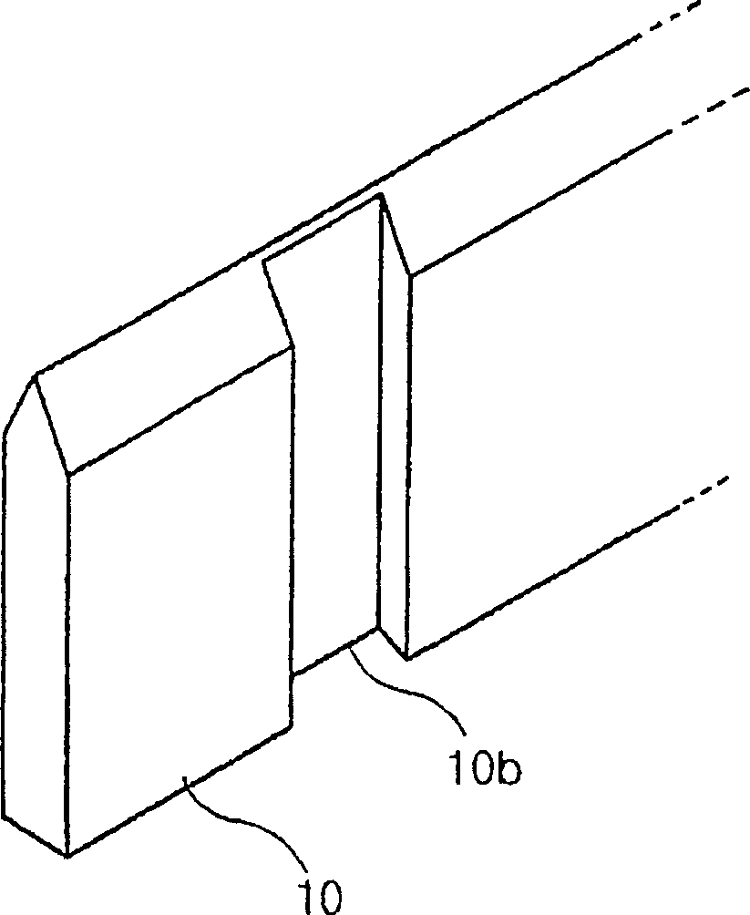
[0034] Figure 1a and 1b A cutting blade 10 is shown having a triangular groove 10a formed with the device of the invention and bent through 90° along this triangular groove 10a. Figure 2a and 2bA cutting blade 10 is shown having a square groove 10b formed with the device of the invention, and another cutting blade 10 is welded into this square groove 10b to form a T-shaped section.

[0035] Figure 3 to Figure 7 is a view for explaining an apparatus for forming a groove on a cutting blade according to the present invention suitable for forming the grooves 10a and 10b.

[0036] In the device for forming grooves in the blade, the cutting blade 10 passes between a pair of broaches 41 supported by tunnel-shaped guides (not shown) in the cutting blade forming device. That is, the device according to the present invention is installed on the ...


PUM


Abstract

The invention discloses a device for forming curved or welded grooves on cutting blades. A pair of fixed blocks are formed on the base of the cutting blade former. A slide block is slidably connected to each fixed block, and a broach supporting block is slidably connected to the slide block. The slide block and broach support block are respectively operated by first and second operating mechanisms. The first to fourth guide parts are formed on the fixed block, the slide block and the broach support block to form a dovetail connection. The first guide part of the fixed block and the second guide part of the slider are formed with inclined surfaces so that they move horizontally close to each other when the slider is lowered. The lower portion of the broach is formed as a support surface, and at least one broaching edge portion is formed over the support surface portion.

Description

technical field [0001] The present invention relates generally to an apparatus for forming grooves in cutting blades, and more particularly to an apparatus for forming grooves in cutting blades, allowing the cutting blades to be easily bent into right or acute angles, or welded to a on the other to form a T-shaped section. Background technique [0002] As is well known to those of ordinary skill in the art, when manufacturing boxes, low-hardness thin sheets such as cardboard, synthetic resin, etc. are initially cut by punching, punching, etc. to prepare initial sheet products. The initial sheet product is processed into the unfolded state of the box, and then, by folding and joining the processed sheet product, the box is completed. [0003] In a process initially performed when manufacturing the box, a cutting blade formed to have a shape corresponding to the unfolded state of the box is mounted on a cutting blade holder having a plate-like shape so that a cutting edge of ...

Claims


Application Information

Patent Timeline
Patent Type & Authority Applications(China)
IPC IPC(8): B23D37/12B23D37/22B23D43/02
CPCB23D37/12B23D37/22B23D43/02Y10T409/4028Y10T409/40455Y10T83/023
Inventor 朴洪顺
Owner 朴 洪顺
Learn More