
Process for vacuum linear source evaporation coating film and its apparatus

An evaporation coating and line source technology, applied in the field of evaporation coating, can solve the problems of low utilization rate of evaporation materials, difficult control, fast evaporation speed, etc., and achieve the effect of increasing effective utilization rate, convenient adjustment and control, and less film defects

Inactive Publication Date: 2005-03-23
成建波
View PDF0 Cites 19 Cited by
  • Summary
  • Abstract
  • Description
  • Claims
  • Application Information

AI Technical Summary

Problems solved by technology

[0003] The key to the vacuum evaporation coating method is the evaporation source. Different materials have different requirements for the evaporation source. For some solid powder materials or liquid materials with low melting points, some existing evaporation source structures such as general evaporation boats, evaporation heaters, Knud Zeng Boxes, etc., cannot well meet the requirements of high utilization rate of evaporation source, fast evaporation speed, and good film uniformity.
[0004] The heating point source using low-temperature evaporation has the following disadvantages: First, the effective utilization rate of the evaporation material is very low, only a few percent of the evaporation material, and the remaining 90% of the material is difficult to recycle, resulting in huge waste of material
According to relevant reports, the utilization rate of evaporation materials has reached more than 30%, but the device structure is very complicated, and most of the materials are still wasted.
Second, point source evaporation coating also has a film uniformity problem. If the distance between the evaporation source and the evaporated substrate is relatively close, the uniformity of the evaporated film cannot be guaranteed. If the distance is long, the utilization rate of the evaporation material will be lower, and Increase the volume of the device
Third, the heating device of the current vacuum evaporation device is built inside the vacuum system. The heating device not only pollutes the vacuum system, but also greatly increases the burden on the vacuum system. It also has the disadvantages of low temperature uniformity and difficult control
It is known that the current evaporation source has not solved the problem of material co-evaporation and the problem of easy control of material evaporation rate.

Method used


Image

  • Process for vacuum linear source evaporation coating film and its apparatus
  • Process for vacuum linear source evaporation coating film and its apparatus
  • Process for vacuum linear source evaporation coating film and its apparatus

Examples


Embodiment Construction

[0023] The present invention is further illustrated by embodiments in conjunction with the accompanying drawings.

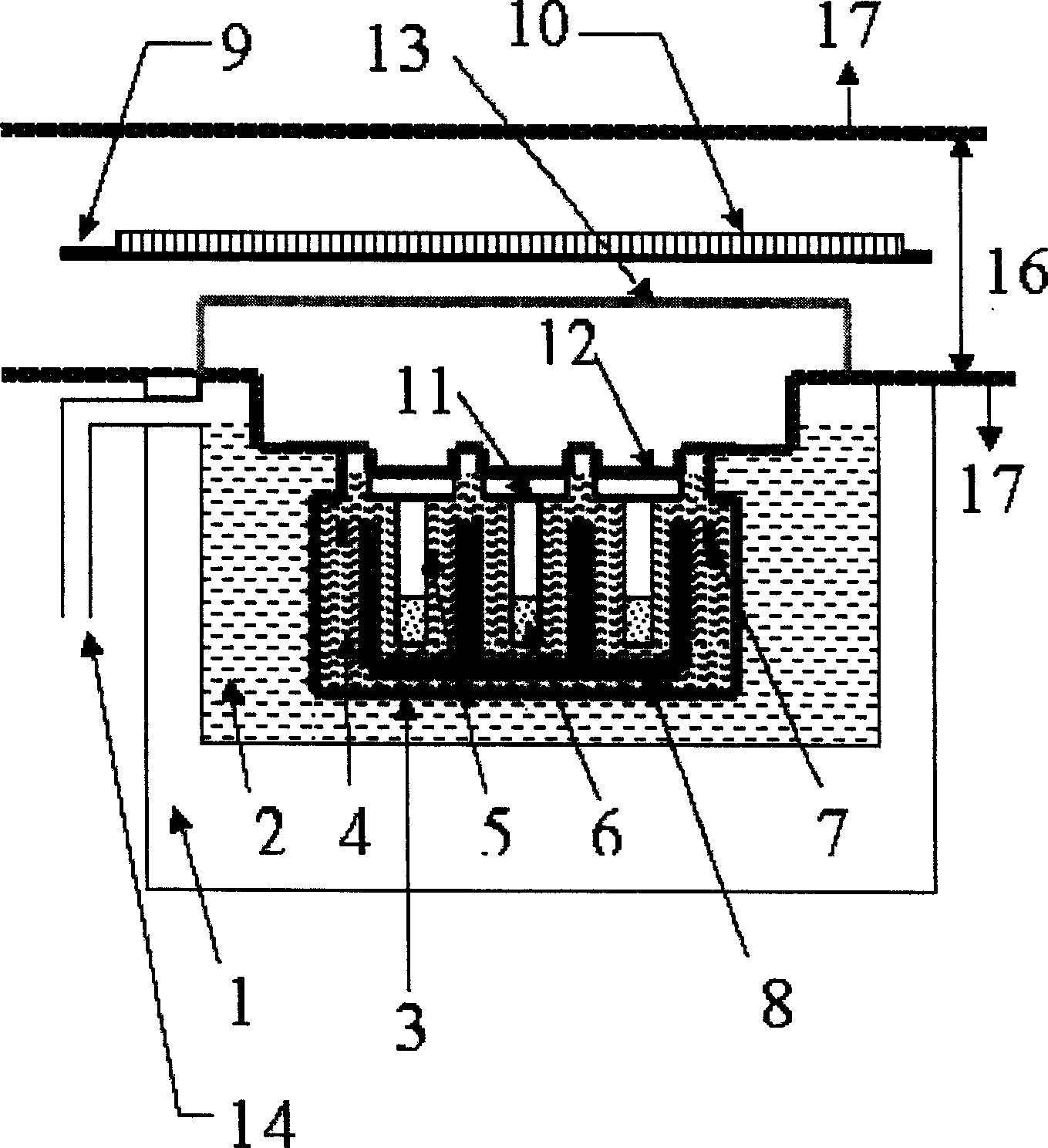
[0024] In the vacuum line source evaporation device of the present invention, the external dimensions of the device are determined according to the size of the coating substrate. The heating source 1 is a precision heater, which is composed of a heater and an oil agitator. The temperature range is 50°C to 350°C, and it contains the first heat-conducting substance 2. There is an air duct 14 to remove the oily fume generated by the first heat-conducting substance. Here, the first heat-conducting substance adopts high-temperature heat-conducting oil, and the temperature non-uniformity of the oil is less than or equal to ±1°C when the temperature of the heater is constant, and the temperature fluctuation of a single point is less than or equal to ±1°C. Both the precision heater 1 and the first heat-conducting substance 2 are placed outside the vacuum system.

[0025...


PUM


Abstract

The method and the equipment of vacuum linear-source vapor filming relate to the technology of vacuum filming. The equipment of the invention is composed of exact heater, vapor cavity filling liquid, vapor boat with concavo-convex trough, milling arm, narrow slot cover board, baffle resisting pollution, switch baffle, thermoscope and so on. Different materials can be put in the flute, processing the basic-quality vapored, intermingled, braized together. The exact heater of the equipment is placed out of the vacuum system. The invention can guarantee the vapor boat and the materials in the boat be heated with symmetrical temperature, stable vapor speed. This invention can improve not only the efficient utilizing rate of vapor materials, but also the vapor plating quality of the thin film.

Description

technical field [0001] The invention relates to a method for evaporation (sublimation) coating in vacuum, and a device for realizing the method, which is used for a linear evaporation source, and is especially suitable for a thin film preparation process by evaporation (sublimation) at a lower temperature. Background technique [0002] There are many methods of film formation of organic materials, including vacuum evaporation (sublimation) coating method, molecular beam epitaxy method, organic chemical vapor deposition method, sol-gel method, etc. Among them, the vacuum evaporation (sublimation) coating method has the advantages of simple operation, easy control of film thickness, little pollution to the film, and easy doping. [0003] The key to the vacuum evaporation coating method is the evaporation source. Different materials have different requirements for the evaporation source. For some solid powder materials or liquid materials with low melting points, some existing ...

Claims


Application Information

Patent Timeline
IPC IPC(8): C23C14/24
Inventor 成建波陈森洁陈文彬杨刚蒋泉王军
Owner 成建波
Learn More