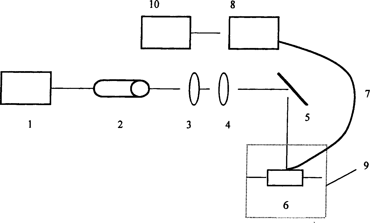
A light scattering detector and capillary tube electrophoresis device for the detector
A technology of capillary electrophoresis and detectors, which is applied in the direction of scattering characteristic measurement, instruments, and measuring devices, and can solve problems such as complex detector equipment
- Summary
- Abstract
- Description
- Claims
- Application Information
AI Technical Summary
Problems solved by technology
Method used
Image
Examples
Embodiment 1
[0030] Embodiment 1: Quantitative detection of hexavalent chromium ion Cr(VI) in the solution in conjunction with a flow injection analyzer.
[0031] The complete set such as Figure 5 shown. exist figure 1 On the basis of the common flow injection analyzer (11), the waste liquid pool (12) is connected. The light source (1) used in this device is a He-Ne laser with a wavelength of 632.8 nanometers and a power of 50 milliwatts. The specification of the optical fiber (7) used is 600 microns in outer diameter.
[0032] Rhodamine B (Rhodamine B, RhB) has very weak laser Rayleigh scattering signal in acidic solution. But in the presence of excess iodide I - After addition, a simple ionic association [RhB][I] was formed and the signal intensity began to increase. At this time, if a trace amount of Cr(VI) is added, the laser Rayleigh scattering signal is significantly enhanced, which is due to the oxidation of Cr(VI) - produce I 2 , with I - combined to form I 3 - , react ...
Embodiment 2
[0034] Embodiment 2: Combined with capillary electrophoresis to detect hexavalent chromium ion Cr(VI) in the solution.
[0035] exist Figure 5 On the basis of , change the flow injection analyzer (11) into a self-assembled capillary electrophoresis instrument, and the others are the same. The detailed structure of the capillary electrophoresis instrument is as follows:
[0036] Please combine Figure 6, (14) is a cuboid plexiglass base, the stainless steel needle of suitable thickness is burned, and the straight main channel is scalded on the plexiglass block top, and the left end (15) of this main channel is arranged with a section of internal diameter 530 microns Capillary, one end of the capillary is placed in the channel (15), and the other end is directly connected with the flow cell (6) in the light scattering detector of the present invention. A section of capillary with an internal diameter of 360 microns is installed in the right channel (16) to transmit the curre...
Embodiment 3
[0045] Embodiment 3: Combined use with micro-liquid chromatography system to detect hexavalent chromium ion Cr(VI) in solution.
[0046] exist Figure 5 On the basis of the above, the flow injection analyzer (11) is changed into a micro-liquid chromatography system, and the others are the same. About the micro liquid chromatography system structure such as Figure 8 Shown: (26) is a miniature liquid chromatography system, (27) is a three-way pool, and (19) is a low-pressure air pump. The principle of the device for detecting Cr(VI) is the same as that in the second embodiment. See Example 2 for the preparation of the current-carrying reagent, and push it into the channel with an air pump. With double redistilled water as the mobile phase, 10 microliters of 0.353 microgram / ml Cr(VI) solution was injected. The results show that it can be used in the detection of micro liquid chromatography system.
PUM
 Abstract
Description
Claims
Application Information
 - R&D
- Intellectual Property
- Life Sciences
- Materials
- Tech Scout
- Unparalleled Data Quality
- Higher Quality Content
- 60% Fewer Hallucinations
Browse by: Latest US Patents, China's latest patents, Technical Efficacy Thesaurus, Application Domain, Technology Topic, Popular Technical Reports.
© 2025 PatSnap. All rights reserved.Legal|Privacy policy|Modern Slavery Act Transparency Statement|Sitemap|About US| Contact US: help@patsnap.com


