
Optical fiber disturbance detection method and apparatus

A detection method and technology of detection device, which are applied to measurement devices, test optical fiber/optical waveguide equipment, and measure ultrasonic/sonic/infrasonic waves, etc., can solve the problems of limited measurement distance, low signal-to-noise ratio, and complicated data processing work. The effect of reducing false positive rate and false negative rate, improving accuracy and sensitivity

Active Publication Date: 2009-07-22
OPTICAL SCI & TECH (CHENGDU) LTD
View PDF0 Cites 36 Cited by
  • Summary
  • Abstract
  • Description
  • Claims
  • Application Information

AI Technical Summary

Problems solved by technology

[0005] Compared with the OTDR-based distributed sensing system, another type of distributed sensing system based on the principle of interferometer has limited measurement distance, low signal-to-noise ratio, is easily affected by various factors, and has a high shielding effect on the reference fiber. requirements, and the data processing work is very complicated, so it is not suitable for real-time security protection of communication optical cables

Method used


Image

  • Optical fiber disturbance detection method and apparatus
  • Optical fiber disturbance detection method and apparatus
  • Optical fiber disturbance detection method and apparatus

Examples


Embodiment

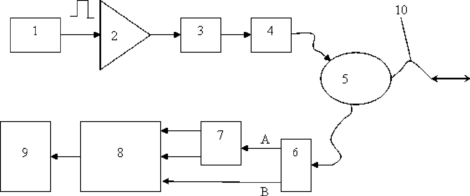
[0034] In the present invention, the detection device is located indoors and mainly includes a DFB laser, an EDFA, a filter, a polarizer, a circulator, a 3dB beam splitter, a polarization beam splitter and a detector. The sensing part (optical fiber) is buried outdoors, and a thin optical cable with a diameter of 3mm made of ordinary single-mode optical fiber is used. Its structure is as follows: figure 1 shown.

[0035] The optical transmitter in this example is composed of DFB (Distributed Feed Back) laser, EDFA (Erbium-doped Optical Fiber Amplifier), filter and polarizer. The DFB laser 1 has an internal modulation function, and the light pulse emitted from it enters the polarizer 4 after being amplified by the EDFA2 and filtered by the filter 3 . In this way, the light pulse injected into the optical fiber 10 through the circulator 5 has a definite polarization state. After the back Rayleigh scattered light in the optical fiber 10 returns to the incident place through the...


PUM


Abstract

The invention relates to an optical fiber sensor. The invention discloses an optical fiber destabilization detecting method combining based on a phase sensitivity light time domain reflection and a polarization sensitivity light time domain reflection method and distributed optical fiber sensing system thereof to improve the detecting accuracy and reliability of the optical fiber destabilization. The method comprises: a. injecting an optical signal with determined polarization state into the optical fiber; b. receiving the back rayleigh scattering light in the optical fiber; c. diving the rayleigh scattering light into two bundles to perform the Phi-OTDR data acquisition and the POTDR data acquisition; d. determining the destabilization and position thereof based on the distortion points of the Phi-OTDR data and the POTDR data. The invention also discloses an optical fiber destabilization detecting device. The technical scheme of the invention is used for monitoring and protecting the optical cable lines, thereby greatly improving the precision and the sensitivity of the monitoring system and reducing the erroneous judgment rate and the missing report rate.

Description

technical field [0001] The invention relates to an optical fiber sensor, in particular to an optical fiber disturbance detection method and a distributed optical fiber sensing system based on the combination of a phase-sensitive optical time-domain reflection method and a polarization-sensitive optical time-domain reflection method. Background technique [0002] With the development of optical fiber communication, especially the rapid development of backbone transmission network, passive optical network and optical fiber access technology, the role of optical fiber cable in the field of communication is becoming more and more important. In today's information age, the accidental interruption of communication caused by the destruction of optical fiber and optical cable will cause immeasurable losses. According to reports, from 2003 to June 2006, there were 61,930 cases of theft and damage of communication optical cables in China Netcom alone. , including 29,364 major cases, c...

Claims


Application Information

Patent Timeline
IPC IPC(8): H04B10/08G01H9/00H04B10/071
CPCG01M11/3181
Inventor 饶云江冉曾令李建中
Owner OPTICAL SCI & TECH (CHENGDU) LTD
Learn More