
Optical fibre transducer general purpose high speed waveguide wavelength scanning demodulation process and apparatus

A technology of optical fiber sensor and waveguide wavelength, which is applied in the direction of transmitting sensing components, measuring devices, instruments, etc. by using optical devices, can solve problems such as poor linearity, difficult process, hysteresis, etc., and achieve linearity and repeatability improvement, integrated optics Effects of process maturity, reliability and life improvement

Inactive Publication Date: 2003-10-15
CHONGQING UNIV
View PDF0 Cites 6 Cited by
  • Summary
  • Abstract
  • Description
  • Claims
  • Application Information

AI Technical Summary

Problems solved by technology

The disadvantages of using this demodulation method are: 1) scanning is a kind of mechanical movement, and its speed is limited by the response frequency of the piezoelectric ceramic element itself. It can only measure signals of a few hundred hertz, and cannot measure signals of higher frequencies ( 1KHz or more); 2) The piezoelectric element has shortcomings such as hysteresis, drift, and poor linearity, which also greatly affect the measurement accuracy, linearity, and measurement repeatability of this demodulation method; 3) In work, the tunable filter In fact, it is a kind of mechanical movement driven by the piezoelectric element. The bonding between the piezoelectric element and the filter is easy to be fatigued and damaged, which affects the service life of the instrument; 4) In order to obtain high resolution, the optical fiber Fapper filter The end face of the optical fiber needs to be coated with a high reflective film, which is difficult and has poor repeatability
[0007] 3. Not universal
Limited by hardware, the above two demodulation methods cannot be automatically adapted according to the characteristics of the sensor, so the versatility is poor
For measurement occasions that require both high-precision fiber-optic sensors and high-speed fiber grating sensors, two sets of measuring instrument systems are required, which increases the complexity of the system and increases the cost of measurement.

Method used


Image

  • Optical fibre transducer general purpose high speed waveguide wavelength scanning demodulation process and apparatus
  • Optical fibre transducer general purpose high speed waveguide wavelength scanning demodulation process and apparatus
  • Optical fibre transducer general purpose high speed waveguide wavelength scanning demodulation process and apparatus

Examples


Embodiment Construction

[0026] The present invention will be further elaborated below in conjunction with accompanying drawing:

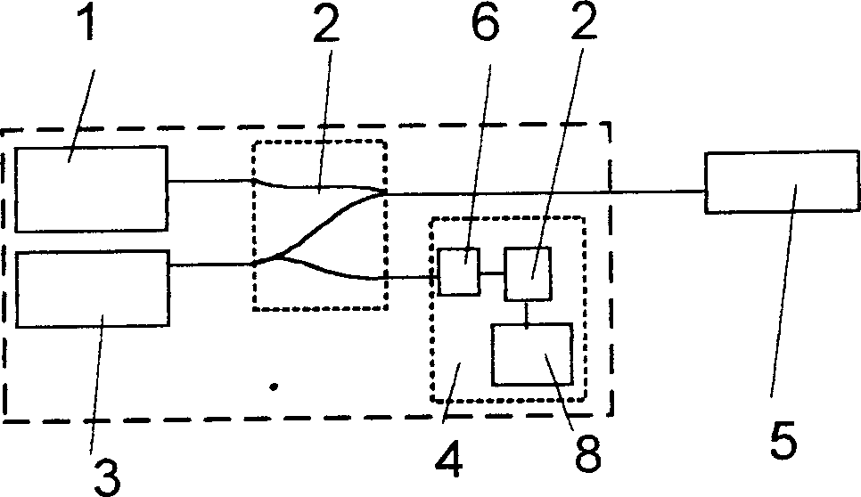
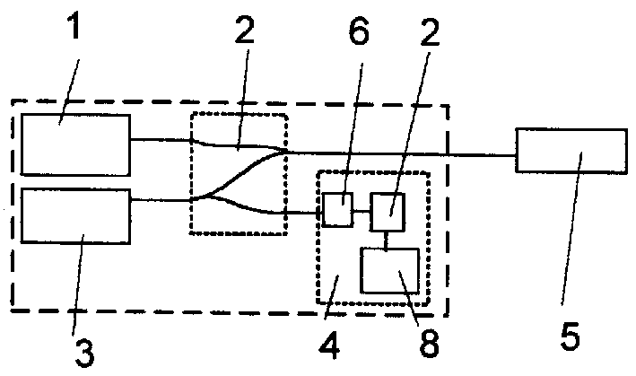
[0027] See attached figure 1 The general-purpose, high-speed waveguide wavelength scanning demodulation device for fiber optic sensors consists of four parts: a broadband superluminescence (SLD) light source 1, a fiber optic path 2, a tunable waveguide filter 3, and a detection and signal processor 4. Fiber optic path 2 is composed of two Y-shaped single-mode fiber beam splitters; its three ports are respectively connected to SLD light source 1, tunable waveguide filter 3, detection and signal processor 4; the other port is used as the optical output of the instrument The / input port is connected with the external optical fiber sensor 5 . see figure 2 , the tunable waveguide filter 3 is composed of three components such as a single-mode optical waveguide 9, a modulator 10, and a Bragg grating 11 integrated on a piece of lithium niobate crystal; wherein the single-mode o...


PUM


Abstract

The key of the general and high speed waveguide wavelength scan demodulating method is to apply periodical scanning voltage signal on a tunable waveguide filter to make the reflected wavelength vary periodically and to realize the scan of spectrum. The initial reflection wavelength, bandwidth, reflectivity and other parameters of the tunable waveguide filter are designed based on the required light source wavelength and demodulation precision of the demodulator; and the filter wavelength scanning range, scanning frequency and other parameters are controlled through altering the amplitude andfrequency of the driving electric signal for the modulator. The equipment consists of light source, fiber optical path, tunable waveguide filter, which comprises single-mode light waveguide, Bragg grating and modulator, and detecting and signal processing device with intelligent distinguish function.

Description

technical field [0001] The invention belongs to the intersection field between the field of optical fiber sensing and the field of state monitoring of civil infrastructure, and specifically relates to a general-purpose, high-speed waveguide wavelength scanning demodulation method and device for an optical fiber sensor. technical background [0002] Compared with other sensors, fiber optic sensors have the advantages of small size, light weight, good flexibility, corrosion resistance, waterproof, anti-electromagnetic interference, and easy interconnection with communication networks. It is an advanced sensor. In recent years, fiber optic sensors, represented by fiber optic F-P sensor and fiber grating sensor, have been applied and promoted in the monitoring of large-scale civilian conditions (strain, temperature, vibration, etc.) such as bridges, dams, power stations, highways, and tunnels. Especially in the long-term online status monitoring of infrast...

Claims


Application Information

Patent Timeline
IPC IPC(8): G01B21/32G01D5/36
Inventor 朱永陈伟民符欲梅
Owner CHONGQING UNIV
Learn More