
Wrist type electric sphygmomanometer, and its application method

An electronic sphygmomanometer and measurement method technology, applied in catheters, cardiac catheters, etc., can solve problems such as increased interference introduction, wristband pressure fluctuations, increased measurement time, etc., to improve accuracy and stability, and eliminate external interference , the effect of improving stability

Inactive Publication Date: 2003-05-21
TANJIN SUNSHINE QPTICS TECH
View PDF0 Cites 26 Cited by
  • Summary
  • Abstract
  • Description
  • Claims
  • Application Information

AI Technical Summary

Problems solved by technology

If a mechanical deflation valve is used to achieve slow deflation, it is difficult to control the opening of the deflation valve under the condition of a small volume; if the opening is slightly larger, the pressure in the wristband will drop rapidly, and the necessary number of pulsation waveforms cannot be guaranteed. Detection, if the opening is slightly smaller, the deflation rate will decrease, and the measurement time will increase significantly, causing discomfort to the measured object and increasing the possibility of interference introduction
Even if the wrist electronic sphygmomanometer adjusts the opening of the air release valve properly during production, it is difficult to ensure that the opening of the air release valve remains unchanged during long-term use
Compared with the signal of the upper arm, the pulsation signal of the wrist is weak, and the bending of the finger during the measurement is easy to cause small fluctuations in the pressure in the wristband
[0008] In short, if a mechanical deflation valve is used, the non-linear deflation caused by the volume change will affect the correct detection of the pulsation waveform
If an electronically controlled deflation valve is used, although a linear deflation at a substantially constant rate can be achieved, a pulsation waveform that is the same as the heart rate cycle will be superimposed on the linear deflation line
If the timing of controlling the electronically controlled air release valve is inappropriate, such as adjusting the opening of the air release valve when the rising edge of the pulsation waveform appears, the pulsation waveform cannot be detected correctly
The current wrist-type electronic sphygmomanometer fails to combine the correct detection of the pulsation waveform during the deflation process to select the control point of the electronically controlled deflation valve

Method used


Image

  • Wrist type electric sphygmomanometer, and its application method
  • Wrist type electric sphygmomanometer, and its application method
  • Wrist type electric sphygmomanometer, and its application method

Examples


Embodiment 1

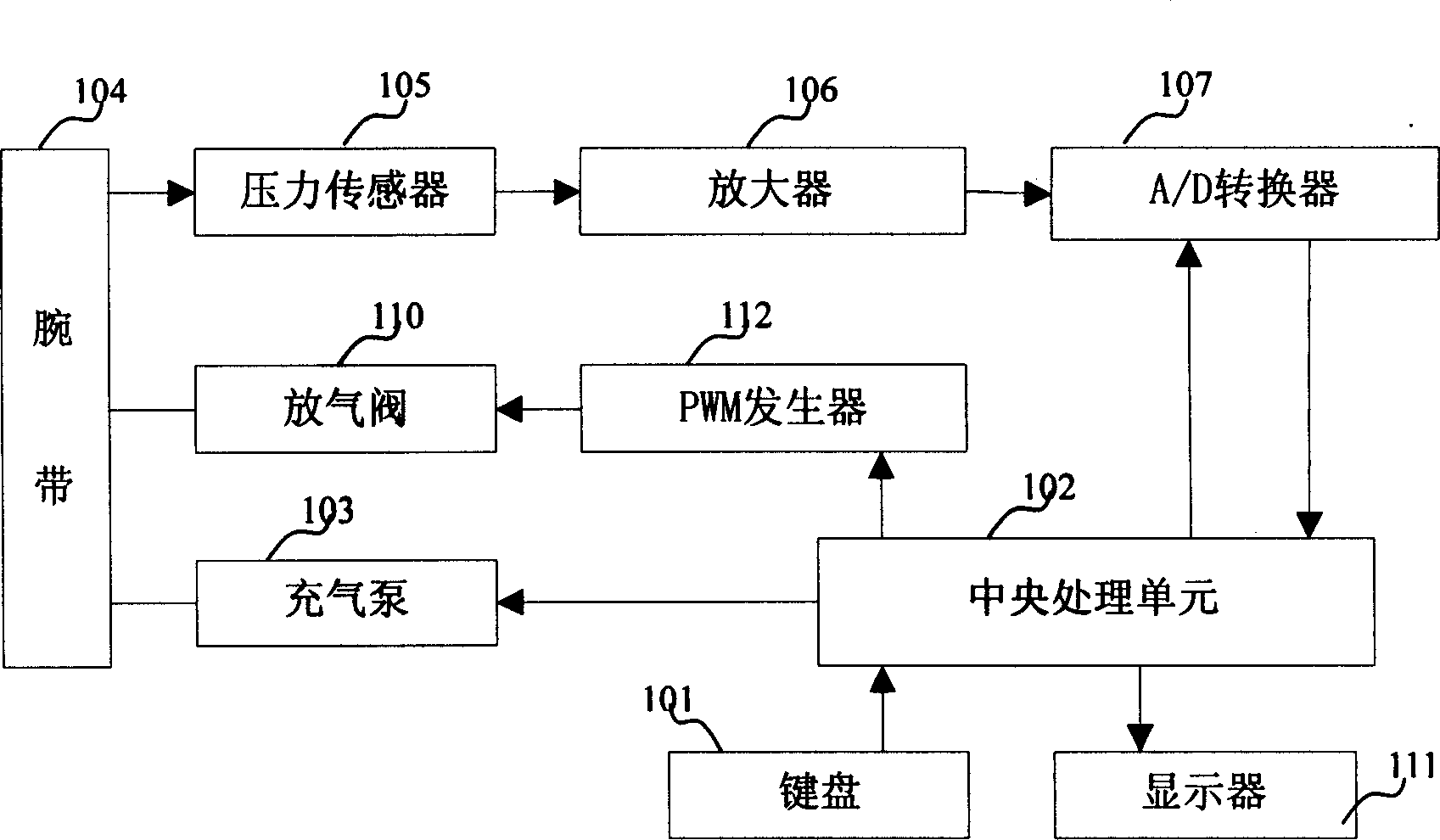
[0062] like Figure 7 As shown, in the initial stage 701 of blood pressure measurement, after the program sets the inflation target pressure value as the initial pressure value of 180 mmHg, as shown in step 702, the programmed deflation valve 110 will be closed, see step 703, and then the central processing unit 102 will start The air pump 103, such as 704, inflates the wristband 104 wrapped around the wrist at this time, and simultaneously controls the PWM generator 109 to generate a signal with a high duty ratio, so that the program-controlled air release valve 110 is basically in a closed state; the central processing unit 102 Continuously detect the pressure in the wristband 104, when the pressure value reaches the inflation target pressure value set by the program 705, stop the air pump 103, and increase the duty cycle of the signal generated by the PWM generator 109, so that the programmed deflation valve 110 can Slowly deflate 706 with a smaller opening, and the central...

Embodiment 2

[0064] After the above process of systolic pressure estimation and inflation pressure automatic judgment is completed, the constant deflation rate control starts. Because in the process of continuous deflation, the pressure oscillation waveform will be superimposed on the curve of continuous pressure drop, such as Figure 4 shown. If the deflation rate is controlled from the starting point of the pressure oscillation wave to the maximum amplitude detection point of the pressure oscillation waveform, there are two problems: one is that the detection of the deflation rate at this stage is difficult to reflect the overall deflation situation of the pressure in the wristband 104; Second, the adjustment of the deflation rate at this stage will affect the correct detection of the maximum amplitude and the first half area of ​​the pressure oscillation waveform. For this reason, the blood pressure measurement method of the present invention judges the current stage during the detecti...

Embodiment 3

[0080] like Figure 10 As shown, this embodiment mainly explains how the central processing unit 102 measures the measurement data corresponding to the historical pressure oscillation waveform according to the maximum amplitude of the pressure oscillation waveform and the envelope curve of the first half area after the wrist electronic sphygmomanometer completes the detection of the pressure oscillation waveform. For comparison, judgment of the same anthropometric data and elimination of singular points are carried out.

[0081] Since the central processing unit 102 of a wrist-type electronic sphygmomanometer of the present invention includes a memory, the memory automatically saves the maximum amplitude and the first half-area envelope of the pressure oscillation waveform measured several times before, as shown in diagram 1002 . In the current measurement process, a wrist-type electronic sphygmomanometer of the present invention obtains the maximum amplitude and the envelope ...


PUM


Abstract

The present invention discloses a wrist electronic sphygmomanometer and its hemadynametry, in which its central processing unit is connected with inflatable pump, PWM generator, comparison voltage generator, voltage comparator, keyboard and display; the wrist band is connected with inflatable pump, electrically-controlled air-discharging vavle and pressure sensor, the described wrist band also isconnected with electrically-controlled air discharging valve, PWM generator and central processing unit, and the described pressure sensor is connected with amplifier, comparison voltage generator, voltage comparator and central processing unit in turn. Said invention also provides its method for measuring blood pressure by using said electronic sphygmomanometer.

Description

technical field [0001] The invention relates to a blood pressure and heart rate measuring device and a measuring method thereof. Background technique [0002] At present, most blood pressure monitors and electronic sphygmomanometers use the oscillometric method to measure blood pressure. The oscillometric blood pressure measurement requires the use of an inflatable cuff or wristband to block the arterial blood flow, and then slowly deflate it. During the deflation process, the gas pressure oscillation wave in the cuff or wristband caused by the pulse of the blood vessel wall is detected. When the pressure in the cuff or wristband is greater than the systolic pressure, the artery is closed, and a small oscillation wave appears in the cuff or wristband due to the impact of the proximal pulse; when the pressure in the cuff or wristband is greater than the mean arterial pressure, the oscillation wave The amplitude gradually increases; when the pres...

Claims


Application Information

Patent Timeline
IPC IPC(8): A61B5/02A61B5/0225
Inventor 胡晓东刘治军
Owner TANJIN SUNSHINE QPTICS TECH
Learn More