
Three-dimensional visual sensor

a three-dimensional visual sensor and sensor technology, applied in the field of three-dimensional visual sensors, can solve the problems of not being able to determine which part of the objective workpiece the reference beam is projected on, no three-dimensional visual sensor which can perform automatic adjustment, and obstacles to work automation, etc., to achieve the effect of measuring accurately

Active Publication Date: 2009-03-10
FANUC LTD
View PDF21 Cites 9 Cited by
  • Summary
  • Abstract
  • Description
  • Claims
  • Application Information

AI Technical Summary

Benefits of technology

[0007]The invention provides a three-dimensional visual sensor which can automatically measure an objective workpiece to obtain required data even when the position and / or orientation of the objective workpiece varies.
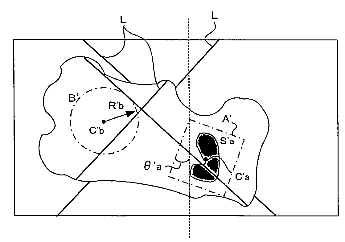
[0009]The reference information may be information on a position and an orientation of the first region and a position and a range of the second region, or alternatively, information on a positional relation between the first and second regions, an orientation of the first region and a range of the second region. In this case, a region corresponding to the second region is determined, based on information on the position and orientation of the region which has been determined as corresponding to the first region in the image of the objective workpiece and the reference information stored in advance, so that the three-dimensional position or orientation of the objective workpiece can be measured accurately even when the position and orientation of the objective workpiece varies.
[0010]The reference information may be information on a position and a size of the first region and a position and a range of the second region, or alternatively, information on a positional relation between the first and second regions, a size of the first region and a range of the second region. In this case, a region corresponding to the second region is determined based on information on the position and size of the region which has been determined as corresponding to the first region in the image of the objective workpiece and the reference information stored in advance, so that the three-dimensional position of the objective workpiece can be measured accurately even when the distance of the objective workpiece from the three-dimensional visual sensor varies.
[0011]The reference information may be information on a position, a size and an orientation of the first region and a position and a range of the second region, or alternatively, information on a positional relation between the first and second regions, a size and an orientation of the first region and a range of the second region. In this case, a region corresponding to the second region is determined based on information on the position, size and orientation of the region which has been determined as corresponding to the first region in the picture of the objective workpiece and the reference information stored in advance, so that the three-dimensional position and orientation of the objective workpiece can be measured accurately even when the distance of the objective workpiece from the three-dimensional visual sensor, and the position and orientation of the objective workpiece vary.

Problems solved by technology

However, in the case of an objective workpiece of which the position and / or orientation on a plane is not settled, or an objective workpiece of which the three-dimensional position and orientation are not settled like workpieces stacked randomly, when the position and orientation of the objective workpiece is measured with the three-dimensional visual sensor, it cannot be determined which part of the objective workpiece the reference beam is projected on, or even whether the reference beam falls on the objective workpiece or not.
However, there is no three-dimensional visual sensor which can perform automatic adjustment, which forms an obstacle to automation of work.

Method used


Image

  • Three-dimensional visual sensor
  • Three-dimensional visual sensor
  • Three-dimensional visual sensor

Examples


first embodiment

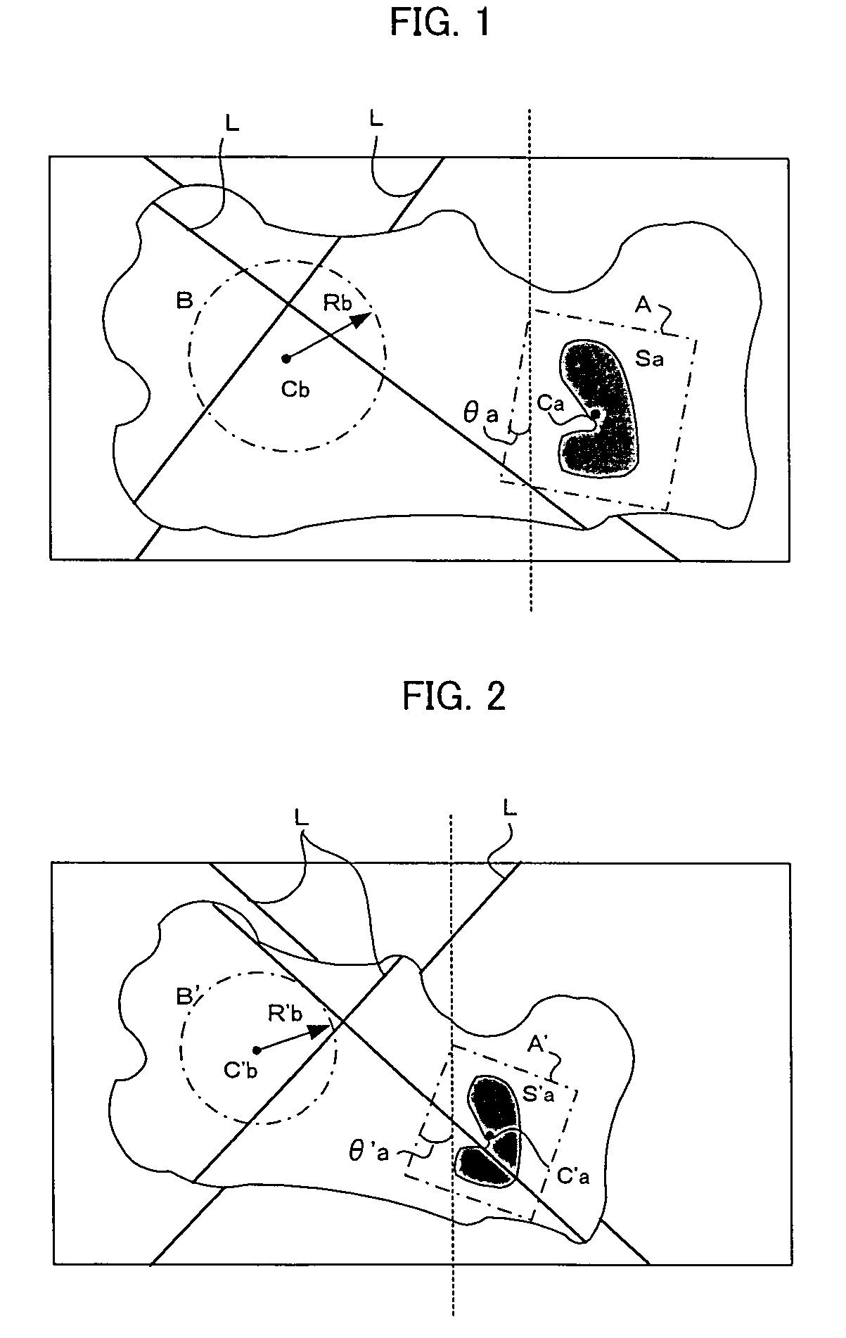
[0023]FIGS. 1 and 2 are illustrations for explaining principles of the invention. FIG. 1 shows an image of a reference workpiece captured by a camera, the reference workpiece having the same shape and size as one of objective workpieces which are objects of operation. A region A is set as a region where a characteristic part of the workpiece (i.e. the reference workpiece of the same type as the objective workpieces) has been detected through two-dimensional image processing. A center position Ca (xa, ya), a tilting angle θa and a size Sa of the region A which includes the characteristic part are detected.

[0024]A region B is set as a region which has been determined as a target region of three-dimensional measurement on the captured image. In the present example, the target region B of three-dimensional measurement is a circle in shape. The center position Cb (xa, ya) of the region B, and the radius Rb of the region B which determines the range of the region B are determined.

[0025]Th...

second embodiment

[0049]FIG. 5 is an illustration for explaining a second embodiment in which the three-dimensional position and orientation of an objective workpiece is measured using information on the distance (height) between the objective workpiece and the sensor section. Suppose that an objective workpiece W is at a short distance D1 from the sensor section 1, and that an image w1 of the objective workpiece is obtained in a picture frame E1 of a camera 1b by projecting a predetermined laser slit beam L from a laser slit beam projector 1a. As shown in FIG. 5, the image w1 of the objective workpiece on which the laser slit beam is projected is at a fixed position in the picture frame E1 which corresponds to the visual field of the camera. Suppose that an objective workpiece W is at a distance D2 from the sensor section 1, and that an image w2 of the objective workpiece W is obtained, projecting the predetermined laser slit beam L likewise. As shown in FIG. 5, the image w2 of the objective workpie...


PUM


Abstract

A three-dimensional visual sensor which measures the three-dimensional position and orientation of an objective workpiece accurately even when the position and orientation thereof varies. The position Ca, tilting angle θa and size S of a first region A which includes a characteristic part of an objective workpiece, and the position Cb and radius Rb of a second region B which is a target region of measurement are determined in a two-dimensional image of a representative objective workpiece captured from a predetermined position, and stored as reference information. An image of a to-be-measured objective workpiece is captured, and in the image, a region corresponding to the second region is determined on the basis of the position C′a, tilting angle θ′a and size S′ of a region corresponding to the first region A, and the reference information. The position and orientation of the objective workpiece is obtained by measuring the region determined as corresponding to the second region.

Description

BACKGROUND OF THE INVENTION[0001]1. Field of the Invention[0002]The present invention relates to a three-dimensional visual sensor for measuring position and orientation of an objective workpiece by projecting a reference beam such as a laser beam onto the objective workpiece and receiving a reflected beam with a camera.[0003]2. Description of Related Art[0004]The three-dimensional visual sensor for measuring the position and orientation of an objective workpiece by projecting a reference beam such as a laser beam onto the objective workpiece and receiving the reflected beam with a camera is used broadly and generally. Regarding the reference beam, various types such as a spot beam and a slit beam are known. Also regarding the beam projecting means, various types such as a type having two light sources and a type which scans an objective workpiece with a single light source and thereby produces effects equivalent to the effects produced by the type having a plurality of light source...

Claims


Application Information

Patent Timeline
IPC IPC(8): G06K9/00B25J19/04G01B11/00G01B11/24G06T1/00G06T7/00
CPCG01B11/00G01B11/24G06T7/0042G06T2207/30164G06T7/73
Inventor BAN, KAZUNORIKANNO, ICHIRO
Owner FANUC LTD
Learn More