Method and equipment for raising speed of electronic cyclotron resonance chemical vapor deposition

An electron cyclotron resonance and chemical vapor deposition technology, applied in the field of plasma, can solve the problems of poor magnetic field distribution uniformity, low film deposition speed, complicated control, etc., and achieve the effects of low manufacturing cost, improved film deposition speed, and small device volume.

Inactive Publication Date: 2003-05-14
BEIJING UNIV OF TECH
View PDF0 Cites 7 Cited by
  • Summary
  • Abstract
  • Description
  • Claims
  • Application Information

AI Technical Summary

Problems solved by technology

[0005] The object of the present invention is that, in the field of electron cyclotron resonance plasma application technology, for the formation and control of the axial magnetic field configuration, the volume is large, the control is complicated and the cost is high when the coil magnetic field is used alone, and the permanent magnet is used only. The problem of poor uniformity of magnetic field distribution, and the resulting low film deposition rate, proposes a new method to solve this problem

Method used


Image

  • Method and equipment for raising speed of electronic cyclotron resonance chemical vapor deposition
  • Method and equipment for raising speed of electronic cyclotron resonance chemical vapor deposition
  • Method and equipment for raising speed of electronic cyclotron resonance chemical vapor deposition

Examples


example 1

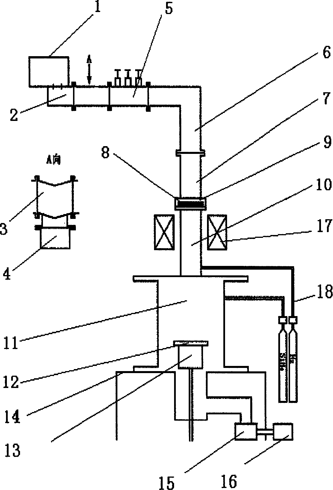
[0024]Example 1: The experimental condition is that the system is evacuated to 1×10 -3 Pa, hydrogen gas is passed into the resonance cavity 10 with a flow rate of 20 sccm, the air pressure is adjusted to 0.5 Pa, a current of 137A is passed into the magnetic field coil 17, and the actual output power of the microwave source 1 is 500W. Electron cyclotron resonance plasma can be generated in the resonant cavity 10 and the deposition chamber 11 under the joint action of the microwave and the coil magnetic field.

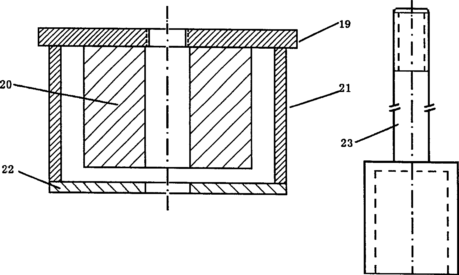
[0025] image 3 and Figure 4 They are the plasma photo when the single coil magnetic field 17 is used and the plasma photo when the single coil 17 magnetic field is combined with the permanent magnet unit 13 magnetic field. The plasma in the single-coil magnetic field is divergent in the vacuum deposition chamber 11; the plasma in the combination of the magnetic field of the single coil 17 and the magnetic field of the permanent magnet 13 unit is divergent in the vacu...

example 2

[0026] Example 2: Put a clean glass sheet with a size of 20mm×20mm×1mm on the sample stage 12, and the system is vacuumed to 1×10 -3 Pa, heat the sample to 280°C, feed hydrogen gas into the resonant cavity 10 with a flow rate of 20 sccm, feed silane into the deposition chamber 11 with a flow rate of 7 sccm, adjust the total air pressure to 0.5 Pa, feed a current of 137A into the magnetic field coil 17, and microwave The actual output power of source 1 is 500W. Under the joint action of microwave and coil magnetic field, electron cyclotron resonance plasma is generated in the resonant cavity 10 and the deposition chamber 11, and the amorphous silicon film is deposited on the glass sheet. The deposition rate of the amorphous silicon film is 5.2 Å / s when the magnetic field of the single coil 17 is used; the deposition rate of the amorphous silicon film is 12.2 Å / s when the magnetic field of the single coil 17 is combined with the magnetic field of the permanent magnet unit 13 . ...


PUM


Abstract

The present invention relates to microwave low temperature plasma technology. The equipment includes microwave source, vacuum sealing, film depositing and vacuum pump systems and magnetic field generating and gas path and gas controlling parts. The magnetic field winding is set around the resonant cavity wall to generate axial magnetic field configuration required by the electronic cyclotron resonance. The present invention is characterized by the permanent magnet unit, which is set over the sample bench to generate homogeneous axial magnetic field in the depositing chamber, and has small volume and thus great moving space in the depositing chamber and great axial magnetic field change. The axial magnetic field configuration is formed and regulated through the combination of the winding and the permanent magnet unit, and the magnetic field configuration results in high film depositing speed.

Description

technical field [0001] A method and device for increasing the speed of electron cyclotron resonance chemical vapor deposition belong to the technical field of microwave low-temperature plasma. Background technique [0002] High-speed deposition of thin films is an important development direction for microwave plasma applications. Electron cyclotron resonance (ECR) plasma is a new type of microwave plasma developed in the past ten years. Due to its high degree of ionization and no electrode pollution, it has been paid more and more attention by people. However, there are still some problems in controlling the axial magnetic field configuration of electron cyclotron resonance plasma in the prior art, resulting in the electron cyclotron resonance CVD thin film deposition rate hovering at a low level. [0003] The configuration of the axial magnetic field in the vacuum deposition chamber plays a crucial role in controlling the shape of the plasma and the deposition rate of the...

Claims


Application Information

Patent Timeline
Patent Type & Authority Applications(China)
IPC IPC(8): C23C16/511C23C16/513
Inventor 陈光华阴生毅宋雪梅
Owner BEIJING UNIV OF TECH
Why Eureka
Try Eureka