
Hydraulic arrester with capabilities of speed adjustment and soft braking

A brake and speed regulation technology, applied in the direction of brakes, liquid resistance brakes, brake types, etc., can solve the problems of hydraulic system heating, malfunction, speeding, etc., achieve smooth and rapid braking, avoid heating problems, and solve pollution effects

Inactive Publication Date: 2003-05-07
TAIYUAN UNIV OF TECH
View PDF0 Cites 29 Cited by
  • Summary
  • Abstract
  • Description
  • Claims
  • Application Information

AI Technical Summary

Problems solved by technology

[0002] For some downward belt conveyors with a large inclination angle, the sliding force generated by the gravity of the material greatly exceeds the running resistance, so that the drive motor runs in the state of power generation, and when the brake is stopped, the sliding force all acts on the braking device On the other hand, it is easy to cause the brake device to fail and cause speeding, causing accidents such as running coal, hurting people, breaking the belt, and the motor rotor is broken.
In response to this situation, many brake devices have been developed at home and abroad. One of the brake devices that is more commonly used and has a better effect is the hydraulic speed control brake. The speed valve is used to adjust the braking force. At present, the maximum operating pressure of the domestic speed control valve is 28Mpa, and the high-pressure and large-flow hydraulic system should generally reach a pressure resistance of 35Mpa, so a base pressure valve must be added to the system, and the base pressure valve distribution The speed regulating valve can work normally only after the pressure of 4~5Mpa
As a result, no matter in braking or non-braking conditions, the base pressure valve is always working under pressure, resulting in heat, which makes the entire hydraulic system heat and cannot work normally.
The second is to use the preset braking law to adjust the braking speed. The control part is simple and no feedback signal is used. The braking torque generated by the hydraulic system cannot be consistent with the braking torque required by the actual working conditions of the tape machine. Belong to open loop control
The third is that the hydraulic brake system generally adopts an open system, and the open system is most susceptible to the influence of the surrounding environment. After the oil is polluted, it often causes the entire system (especially the important valve parts) to fail to work normally.

Method used


Image

  • Hydraulic arrester with capabilities of speed adjustment and soft braking
  • Hydraulic arrester with capabilities of speed adjustment and soft braking
  • Hydraulic arrester with capabilities of speed adjustment and soft braking

Examples


Embodiment Construction

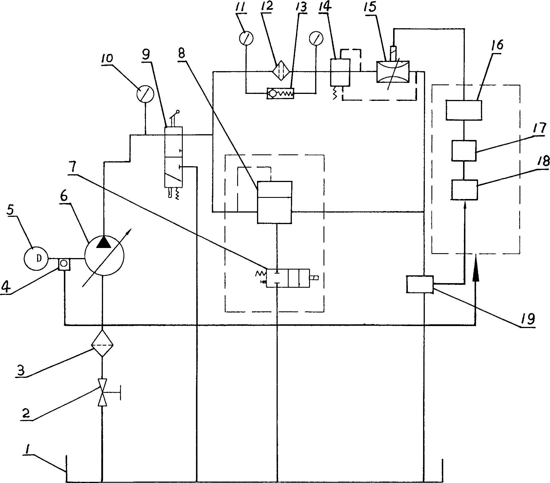
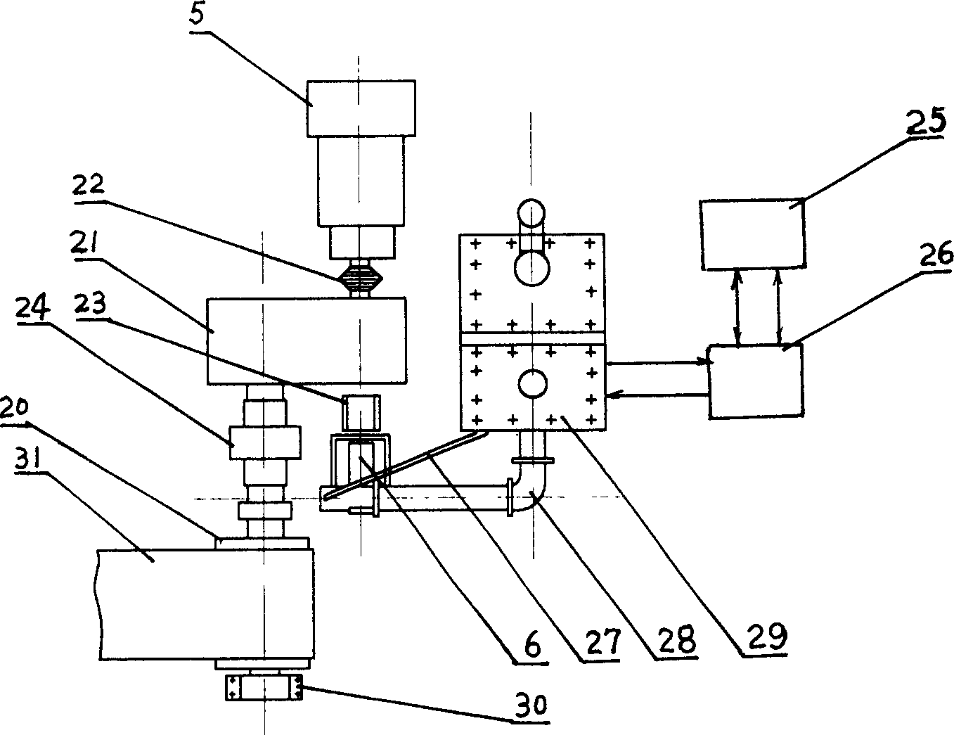
[0012] The hydraulic variable speed soft brake is a subsystem that must be used in conjunction with the braked system (main system). The motor 5 of the main system is connected with the reducer 21 of the belt conveyor through a coupling 22, and the output shaft of the reducer 21 directly drives the driving roller 20 of the conveyor. The oil suction port and the oil discharge port of the brake pump 6 are connected to the hydraulic pump station 29 respectively. Manual reversing valve 9, pilot relief valve 8, electromagnetic reversing valve 7, proportional throttle valve 15, differential pressure reducing valve 14, fine filter 12, coarse filter 3, bypass valve 13, fuel tank 1, The pressure gauges 10 , 11 , the stop valve 2 , the flow sensor 19 and the rotational speed sensor 4 are all arranged in the hydraulic pump station 29 . The brake pump 6 is connected with the speed reducer 21 high-speed shaft of the tape machine through a shaft coupling 23, so that the main system drives ...


PUM


Abstract

A hydraulic speed regulation type soft brake for the underhung conveyer is composed of hydraulic system and electric control system. The said hydraulic system consists of braking pump and hydraulic pump station which comprises manual reverse valve, electromagnetic overflow valve, proportional throttle valve, filters, oil tank, pressure meter, cut-off valve and sensors (flow sensor and rotation speed sensor). Its advantages are high braking stability, and no need of cooler.

Description

Technical field [0001] The invention relates to a hydraulic speed regulating brake device. It is especially suitable for use in conjunction with mechanical systems that must be braked, such as conveyor belt conveyors. Background technique [0002] For some downward belt conveyors with a large inclination angle, the sliding force generated by the gravity of the material greatly exceeds the running resistance, so that the drive motor runs in the state of power generation, and when the brake is stopped, the sliding force all acts on the braking device On the other hand, it is easy to cause the brake device to fail and cause speeding, causing accidents such as running coal, hurting people, broken belts, and motor rotors being damaged. In response to this situation, many brake devices have been developed at home and abroad. One of the brake devices that is more commonly used and has a better effect is the hydraulic speed control brake. The speed valve is used to adjust the brak...

Claims


Application Information

Patent Timeline
IPC IPC(8): B60T10/00B60T13/66B65G23/26E21F13/10F16D57/06
Inventor 寇子明李军霞谭鹏辉程仰瑞高贵军
Owner TAIYUAN UNIV OF TECH
Learn More