
Special pulse bag-type dust collector for purifying tail gas of closed submerged arc furnace

A technology of tail gas purification and pulse bagging, which is applied in the direction of chemical instruments and methods, separation methods, and separation of dispersed particles, can solve problems such as no good solutions, hidden safety hazards, and flash explosion accidents, so as to ensure the horizontal pressure operation of equipment , Prevent flash explosion and protect equipment safety

Pending Publication Date: 2022-06-28
湖北江环环保科技有限公司
View PDF0 Cites 0 Cited by
  • Summary
  • Abstract
  • Description
  • Claims
  • Application Information

AI Technical Summary

Problems solved by technology

[0002] The pulse bag filter of the prior art, when dedusting the dust that is easy to deflagrate, uses ordinary compressed air to blow and clean the dust. Since the compressed air is rich in oxygen, it is easy to cause a flash explosion accident, which has a great potential safety hazard. There has been no good solution for this defect

Method used


Image

  • Special pulse bag-type dust collector for purifying tail gas of closed submerged arc furnace
  • Special pulse bag-type dust collector for purifying tail gas of closed submerged arc furnace
  • Special pulse bag-type dust collector for purifying tail gas of closed submerged arc furnace

Examples


Embodiment 1

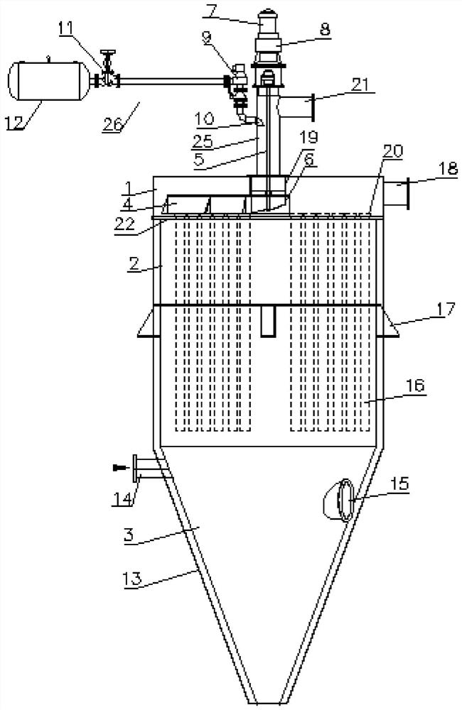
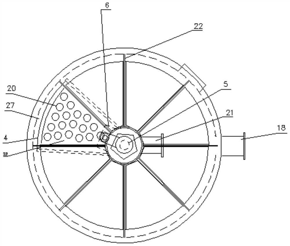
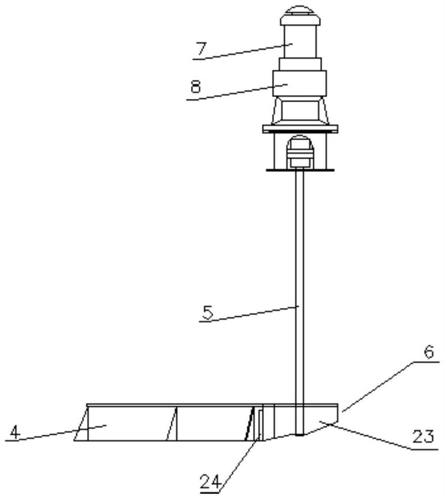
[0023] The main body of the dust cleaning rotary nozzle 6 is a cylinder 23, the left side wall of the cylinder 23 is welded with the enclosure plate at the straight edge of the fan surface of the dust cleaning rotary cover 4, and the cylinder 23 of the dust cleaning rotary nozzle 6 is facing the side of the fan surface A nozzle 24 communicating with the cylinder 23 is provided, and a guide pipe 19 is arranged in the middle of the upper casing 1. The upper end of the guide pipe 19 is vertically welded with the upper casing 1 and communicated with the dust cleaning and blowback pipe 25. The lower end of the flow pipe 19 is provided with a bearing sleeve and the lower end of the bearing rotatably fixed rotating shaft 5 at the position of the tube axis.

Embodiment 2

[0025] The right side of the upper box body 1 is provided with an exhaust gas purification outlet pipe 18, the left side of the ash hopper 3 is provided with an exhaust gas ash accumulation pipe 14, the right side of the ash hopper 3 is provided with an inspection manhole door 15, and the middle end of the middle box body 2 is provided for The column support platform 17 supporting the pulse bag filter for exhaust gas purification of closed submerged arc furnace.

Embodiment 3

[0027] The nitrogen ash cleaning device 26 includes a compressed nitrogen gas storage tank 12 , a control valve 11 , a pulse valve 9 , and a ash cleaning nozzle 10 .


PUM


Abstract

A special pulsed jet cloth filter for tail gas purification of a closed submerged arc furnace comprises an upper box body, a middle box body and an ash bucket, the upper end of the middle box body and the lower end of the upper box body are communicated through a pattern plate and a filter bag, the lower end of the middle box body is communicated with the upper end of the ash bucket, the upper box body and the middle box body are both of a cylindrical structure, and the ash bucket is of a conical structure. An ash removal rotating cover and an ash removal rotating nozzle are arranged in the upper box body and fixed to the lower end of the rotating shaft, a pipe shaft of an ash removal back-blowing pipe is perpendicular to the upper end face of the upper box body and arranged in the center of the upper box body, the ash removal back-blowing pipe is communicated with the upper box body, and a gear motor is fixed to the upper end of the ash removal back-blowing pipe in a sealed mode. The left side of the ash-cleaning back-blowing pipe is communicated with an ash-cleaning spray pipe of the nitrogen ash-cleaning device, the right side of the ash-cleaning back-blowing pipe is communicated with a gas conveying pipe of a back-blowing system, the overlook structure of the ash-cleaning rotary cover is fan-shaped or circular, and a surrounding plate perpendicular to the fan-shaped or circular surface is arranged on the periphery of the fan-shaped or circular surface.

Description

technical field [0001] The invention belongs to the technical field of pulse bag dust removal equipment, and in particular relates to the technical field of pulse bag dust collectors for exhaust gas purification of closed submerged arc furnaces. Background technique [0002] The pulse bag filter in the prior art uses ordinary compressed air for blowing and cleaning when removing dust that is prone to detonation. Since the compressed air is rich in oxygen, it is easy to cause a flash explosion accident, and there is a great potential safety hazard. There has been no good solution to this defect. SUMMARY OF THE INVENTION [0003] The purpose of the present invention is to overcome the deficiencies of the prior art and provide a special pulse bag filter for airtight submerged arc furnace tail gas purification, including: an upper box, a middle box, an ash hopper, the upper end of the middle box and the upper box of the upper box. The lower end is communicated with the upper ...

Claims


Application Information

Patent Timeline
IPC IPC(8): B01D46/02B01D46/04
CPCB01D46/02B01D46/04
Inventor 关成新刘军场杨耘
Owner 湖北江环环保科技有限公司
Learn More