Method for mfg. parallel capacitor core, and parallel capacitor core

A manufacturing method and capacitor technology, applied in the direction of capacitor manufacturing, capacitors, multiple fixed capacitors, etc., can solve the problems of capacitor breakdown, overheating of surrounding media, low dielectric strength, etc., to improve partial discharge performance, avoid melting and Shrinkage and the effect of ensuring compressive strength

Inactive Publication Date: 2003-03-12
锦州电力电容器有限责任公司
View PDF0 Cites 2 Cited by
  • Summary
  • Abstract
  • Description
  • Claims
  • Application Information

AI Technical Summary

Problems solved by technology

[0004] 1. Since the upper and lower ends are single-track and welded in a large area, the oil-immersed parts of the medium and the end faces of the electrodes are sealed in a large area, so that the oil-immersed parts of the full-film capacitor can only be in the small area left on both sides of the weld bead Vacuum degassing and oil immersion, which brings more difficulties to media impregnation
If the oil is impermeable to the medium, then the dielectric strength of the medium between the electrodes is low, and the breakdown phenomenon is serious, which will cause damage. Therefore, it must be soaked. At the same time, poor degassing is a major cause of partial discharge, and partial discharge is One of the biggest hazards of capacitors
[0005] 2. Due to the large welding area of ​​the weld bead, the heat is concentrated, and it is difficult to dissipate the heat in a short period of time, so it is easy to overheat the surrounding medium, causing burns to the surrounding medium, and capacitor breakdown often occurs here
[0006] 3. The single-width bead welding method can only increase the process time in order to fully soak the medium, resulting in a lot of waste of manpower and material resources
And even if the process time is increased, the pass rate of the product will not be effective

Method used


Image

  • Method for mfg. parallel capacitor core, and parallel capacitor core
  • Method for mfg. parallel capacitor core, and parallel capacitor core
  • Method for mfg. parallel capacitor core, and parallel capacitor core

Examples


Embodiment 1

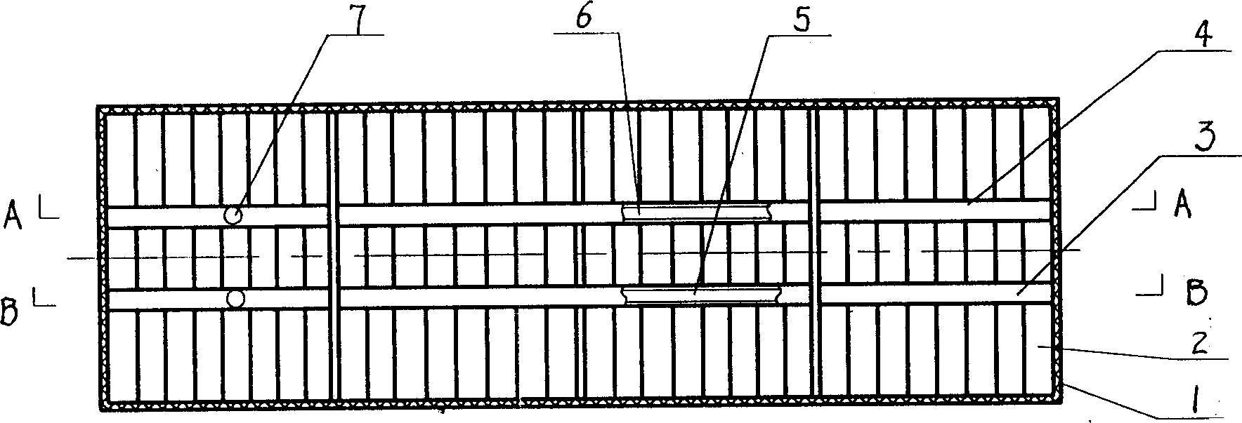
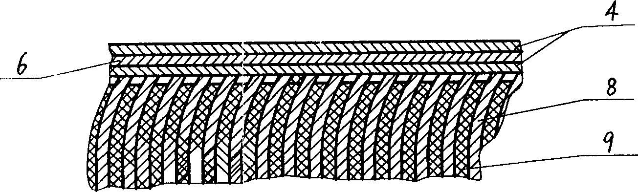
[0020] As shown in the figure, take the aluminum foil 8 and the polypropylene film 9 and place them on the rolling machine for rolling; assemble the rolled components 2 into a core group; place the core group on the workbench, and set the Parallel connection, welding is performed on the upper end surface of the core group along the vertical direction of the side of the component to form a weld bead 3; then reverse welding is performed on the upper end surface of the core group in the opposite direction to the weld bead 3 to form another weld bead 4, two weld bead 3 , 4 leave gap between; Carry out welding with the same method at the lower end face of core group, also form weld bead 3,4, weld lead wire 7 respectively on weld bead 3,4, make capacitor core after packing with cable paper 1.

Embodiment 2

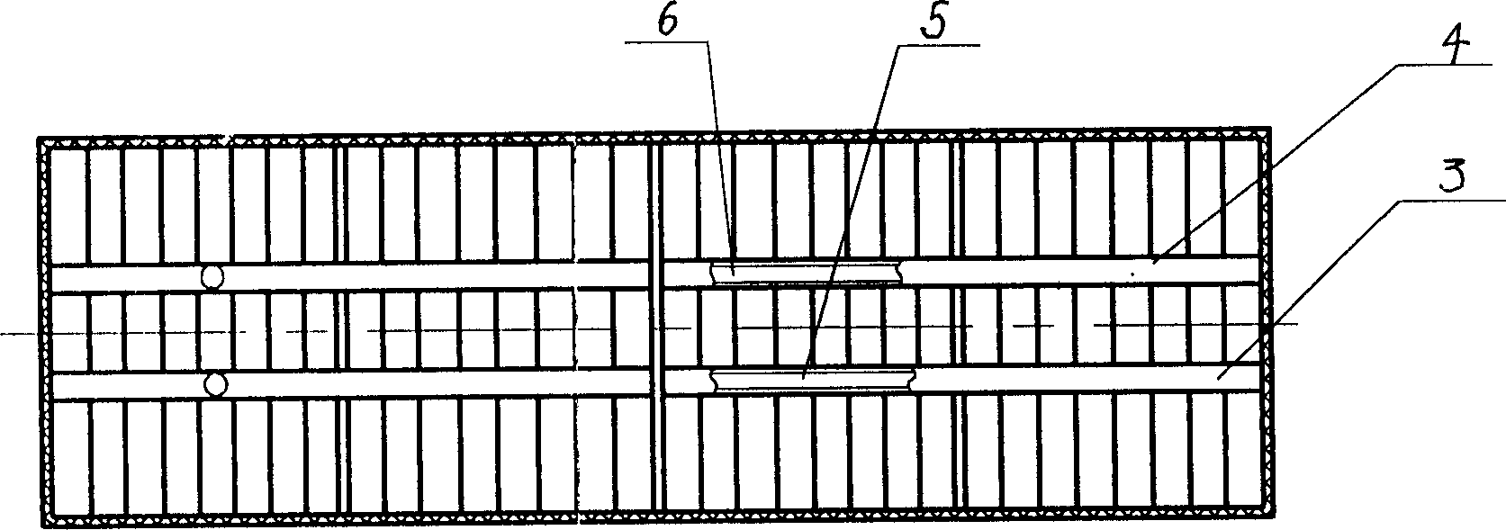
[0022] As shown in the figure, take the aluminum foil 8 and the polypropylene film 9 and place them on the rolling machine for rolling; assemble the rolled components 2 into a core group; place the core group on the workbench, and set the Parallel relationship, weld the upper end face of the core group along the direction of the vertical component side to form a weld bead 3, and bury the metal connecting piece 5 on the weld bead 3 to prevent the weld bead 3 from breaking; 3 Weld the opposite direction to perform reverse welding to form another weld bead 4, and bury the metal connecting piece 6 on the weld bead 4 to prevent the weld bead 4 from breaking, and leave a gap between the two weld bead 3, 4; The lower end face of the group is welded with the same welding method to form another two weld beads 3, 4, and metal connecting pieces 5, 6 are also buried and welded on the weld beads 3, 4; the weld beads 3, 6 on the upper and lower end faces of the core group 4 Solder the lead ...

Embodiment 3

[0024] The shunt capacitor core has a core group consisting of several elements 2, said elements 2 are made of aluminum foil 8 and polypropylene film 9 rolled together, and there are two welding beads 3 and 3 on the upper and lower end faces of the core group respectively. 4. The welding directions of the welding beads 3 and 4 are opposite, and there is a gap between the welding beads 3 and 4, the aluminum foil 8 and the polypropylene film 9 near the welding beads 3 and 4 are twisted, and the twisting direction is opposite , lead wires 7 are respectively welded on the weld beads 3 and 4, and cable paper 1 is wrapped on the surface of the core group.


PUM


Abstract

A parallel capacitor core is prepared through preparing aluminium foil and dielectric film, rolling, assembling core set, welding to form two welding seams, welding leading wire, and packing. its advantages are high oil-immersing speed and quality, improved local discharge performance and short period. Said parallel capacitor core is composed of core set and packing paper.

Description

technical field [0001] The invention belongs to a power capacitor, in particular to a manufacturing method of a parallel capacitor core and the parallel capacitor core. Background technique [0002] Capacitor elements can be divided into two types: convex foil type and hidden foil type. Among them, the hidden foil type uses lead sheets to lead the electrodes out, while the convex foil type directly welds the protruding aluminum foil with low-temperature solder. Because the lead sheet used in the hidden foil capacitor element will cause poor contact between the lead sheet and the aluminum foil, therefore, the hidden foil capacitor element will generate sparks due to poor contact during use, damage the medium, and affect the life of the capacitor; In addition, Since the connection method of the hidden foil capacitor element is crimping, the greater the compression coefficient, the stronger the connection, but because the compression coefficient is too large, it is not only di...

Claims


Application Information

Patent Timeline
IPC IPC(8): H01G4/38H01G13/00
Inventor 刘雪厚石力李丽颖
Owner 锦州电力电容器有限责任公司
Why Eureka
Try Eureka