Eureka AIR delivers breakthrough ideas for toughest innovation challenges, trusted by R&D personnel around the world.

Semiconductor ceramic with negative resistance temperature coefficient and negative temperature coefficient thermistor

A technology with negative temperature coefficient and temperature coefficient, which is applied in the field of semiconductor ceramics and negative temperature coefficient thermistors, can solve the problems of molded body expansion, deterioration of plasticity, etc., and achieve the effect of expansion suppression and good reliability

Inactive Publication Date: 2002-05-08
MURATA MFG CO LTD
View PDF1 Cites 47 Cited by
  • Summary
  • Abstract
  • Description
  • Claims
  • Application Information

AI Technical Summary

Problems solved by technology

[0005] However, according to the methods described in the above-mentioned papers and patent application publications, since free water-soluble barium ions tend to remain in the raw material and sintered product, gelation of the binder will deteriorate the plasticity, and oxides of rare earth elements that have not acted will stays, thus causing swelling of the molded body due to moisture absorption, creating new performance issues in high humidity environments

Method used


Image

  • Semiconductor ceramic with negative resistance temperature coefficient and negative temperature coefficient thermistor
  • Semiconductor ceramic with negative resistance temperature coefficient and negative temperature coefficient thermistor

Examples


Embodiment 1

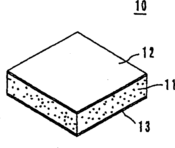
[0022] mn 3 o 4 with BaCO 3 Raw materials were prepared by mixing so that the atomic ratio of Ba / M became 1. After firing at 1300°C for 2 hours, the raw materials were crushed with a pulverizer, and then finely ground with a ball mill for 20 hours to obtain BaMnO 3 powder.

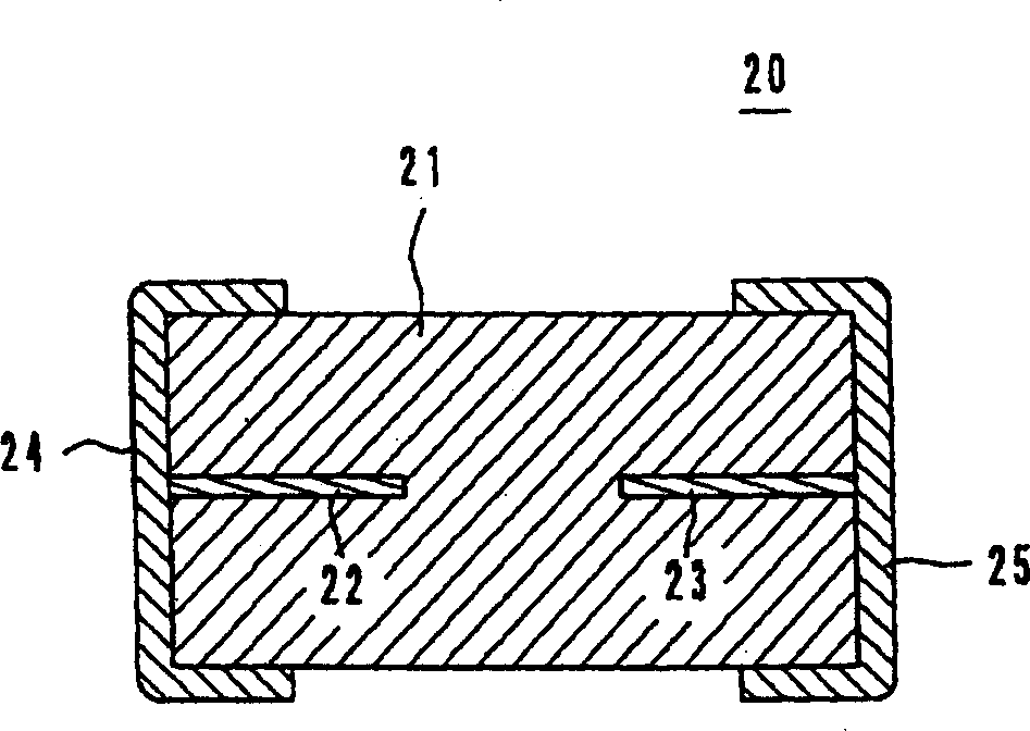
[0023] Then as listed in Table 1, the BaMnO 3 Powder was added to Mn with a weight ratio of 50:30:20 3 o 4 , NiO and Fe 2 o 3 In, mixed with a ball mill for 16 hours. The raw material was fired at 900°C for 2 hours and crushed with a pulverizer. Next, 10% by weight of polyvinyl alcohol as an organic binder, 0.5% by weight of glycerin as a plasticizer and 1.0% by weight of a polyethylene dispersant were added to the crushed raw material and mixed for 16 hours. Then, coarse particles were removed with a 250-mesh sieve to obtain sheet-shaped pulp. This slurry was formed into a 50 μm thick ceramic green sheet with a doctor blade.

[0024] Punch the ceramic green sheet into a fixed size, and stack t...

Embodiment 4

[0041] La 2 o 3 , SrCO 3 with MnCO 4 Raw materials were prepared by mixing so that the atomic ratio Sr:La:Mn=0.05:0.95:1. After firing at 800°C for 2 hours, crush the raw material with a pulverizer, and then finely grind it with a ball mill for 20 hours to obtain Sr 0.5 La 0.95 MnO 3 powder.

[0042] Next, the Sr listed in Table 4 0.5 La 0.95 MnO 3 Powder was added to Mn with a weight ratio of 45:25:30 3 o 4 , Fe 2 o 3 with Co 3 o 4 Li, and mixed with a ball mill for 16 hours. The raw material was fired at 900°C for 2 hours and crushed with a pulverizer. Next, 10% by weight of polyvinyl alcohol as an organic binder, 0.5% by weight of glycerin as a plasticizer and 1.0% by weight of a polyethylene dispersant were added to the crushed raw material and mixed for 16 hours. Then, coarse particles were removed with a 250-mesh screen to obtain a sheet-shaped slurry, which was formed into a 50-μm-thick ceramic green sheet with a doctor blade.

[0043] The ceramic gree...


PUM


Abstract

A semiconductor ceramic having a negative temperature coefficient of resistance, the element comprising about 0.1 to 20 mol % of AMnO3 (A represents at least one of Ca, Sr, Ba, La, Pr, Nd, Sm, Eu, Gd, Th, Dy and Ho) and to a spinel composite oxide made of a solid solution of Mn and at least one element in Ti, V, Cr, Fe, Co, Ni, Cu, Zn, Mg and Al. As a perovskite Mn composite oxide, one or more of CaMnO3, SrMnO3, BaMnO3, LaMnO3, PrMnO3, NdMnO3, SmMnO3, EuMnO3, GdMnO3, TbMnO3, DyMnO3 and HoMnO3 may be used.

Description

technical field [0001] The invention relates to a semiconductor ceramic with a negative temperature coefficient of resistance and a negative temperature coefficient thermistor. Background technique [0002] In recent years, there has been a demand for more precise NTC thermistors, which are mainly used as temperature sensors, and are also required to control the change in resistance to around ±1%. Usually, in this type of negative temperature coefficient thermistor, the spinel composite oxide composed of Mn solid solution and at least one element among Zn, Mg and Al and transition elements (Ti, V, Cr, Fe, Co, Ni, Cu) are used as semiconductor ceramics for this NTC thermistor. However, it is generally known that complex oxides cause problems in environmental resistance. It is believed that the problem is caused by the Mn ions changing their oxidation state and migrating between lattice sites when the ambient temperature and oxygen partial pressure change. [0003] To solve...

Claims


Application Information

Patent Timeline
IPC IPC(8): C04B35/00C04B35/01H01C7/04
CPCB32B2311/08C04B2235/3293C04B2235/3215C04B2237/704C04B2235/3217C04B2235/3205H01C7/045C04B2235/3208C04B2235/3277B32B18/00C04B2235/3268C04B2235/3213C04B2235/3227C04B2235/3263C04B2235/3279C04B2235/763C04B2237/408C04B2235/3262C04B35/016C04B2237/34C04B2235/3272C04B2235/3224H01C7/043C04B2235/3275H01C7/04
Inventor 中山晃慶藤田聡
Owner MURATA MFG CO LTD
Why Eureka
Eureka Blog
Learn More