Efficient electric power generation method

A technology for heavy oil and crude oil, applied in combustion methods, engine components, machines/engines, etc., which can solve problems such as no processing burden, heat loss of exhaust gas, etc.

Inactive Publication Date: 2005-03-23
MITSUBISHI HEAVY IND LTD
View PDF1 Cites 0 Cited by
  • Summary
  • Abstract
  • Description
  • Claims
  • Application Information

AI Technical Summary

Problems solved by technology

[0005] The present invention has been made in view of the above circumstances, and therefore one of its objects is to provide a high-efficiency power generation method in which a heating furnace is not used, so that the problem of heat loss of exhaust gas is solved, and the power generation system is not burdened with treating SOx and NOx in exhaust gas, thereby The power generation efficiency of the exhaust gas reburning system is further improved as a whole

Method used


Image

  • Efficient electric power generation method
  • Efficient electric power generation method
  • Efficient electric power generation method

Examples


Embodiment Construction

[0016] The high-efficiency power generation method of the present invention will be described below with reference to an embodiment shown in the accompanying drawings.

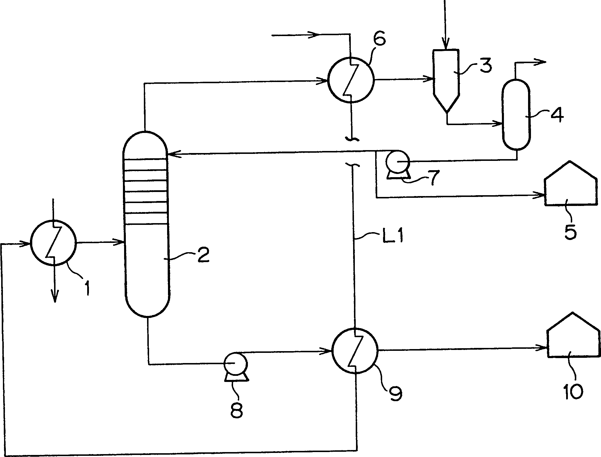
[0017] figure 1 is a schematic diagram showing the layout of an embodiment of a system for separating crude oil or heavy oil by distillation of a system for implementing the high-efficiency power generation method of the present invention by using an exhaust gas reburning system;

[0018] The distillation equipment of this embodiment includes a heater 1 , a vacuum distillation column 2 and a steam ejector 3 .

[0019] The heater 1 as a device for heating crude oil or heavy oil heats crude oil or heavy oil by heat exchange between steam and crude oil or heavy oil. Steam is supplied from a boiler (not shown). The steam obtained from the boiler is sent to a steam turbine to turn it, thereby generating electricity. The steam supplied to the heater 1 is the steam which once rotated the steam turbine to generate ...


PUM


Abstract

In a high-efficiency power generating method to generate electric power by an exhaust gas re-combustion system using at least a gas turbine, a boiler, and a steam turbine, crude oil or heavy oil is heated with steam obtained from the boiler; the crude oil or heavy oil is distilled under reduced pressure; and electric power is generated by using an obtained light oil fraction as a gas turbine fuel and by using a heavy oil fraction as a boiler fuel.

Description

technical field [0001] The invention relates to a high-efficiency power generation method. Background technique [0002] In recent years, power plants have conducted research on the fractionation of crude oil or heavy oil. Light oil fractions (low boiling point components) obtained by fractional distillation are sent to a gas turbine where they are combusted to generate electricity. The high-temperature combustion exhaust gas obtained by the gas turbine is sent to a boiler instead of air, and the heavy oil fraction (high-boiling point components) is burned in the boiler, and a steam turbine is rotated by the high-temperature, high-pressure steam generated in the boiler to generate electricity. That is, there is provided a method in which power generation is performed simultaneously with so-called re-powering in which exhaust gas from a gas turbine is charged into a boiler and recombusted. [0003] As a means of distilling crude oil or heavy oil, atmospheric and vacuum dist...

Claims


Application Information

Patent Timeline
IPC IPC(8): F01K17/06F01K21/04F01K23/02F01K23/10F02C3/20F02C3/24F02C7/22F23K5/08
CPCF01K23/103Y02E20/16F01K23/10
Inventor 饭岛正树小林一登森胁正文柴田正俊百武慎德
Owner MITSUBISHI HEAVY IND LTD
Why Eureka
Try Eureka