Manufacturing method of heat insulating oil casing

A manufacturing method and oil casing technology, which is applied in the fields of oil production tools and its manufacture, the manufacture of heat-insulated oil casing, and steam injection, and can solve the problems of heat loss at coupling joints, cementing casing damage, and waste of economic benefits and other problems, to achieve the effect of improving heat insulation performance, prolonging heat insulation life, and solving the problem of sleeve damage

Active Publication Date: 2016-04-20
淄博孚瑞特热能科技有限公司
View PDF9 Cites 0 Cited by
  • Summary
  • Abstract
  • Description
  • Claims
  • Application Information

AI Technical Summary

Problems solved by technology

The current heat-insulated oil pipes are all produced according to or with reference to a "vacuum heat-insulated oil pipe and its manufacturing process" disclosed in the Chinese patent (application number 97115719.7). Tube, heat insulation layer, centralizing block, hydrogen absorbing agent, etc., wherein the structure of the heat insulating layer is: the inner tube is multi-layer aluminum foil, glass mesh is wound at intervals, the annular space is evacuated, and hydrogen absorbing agent is added. This kind of manufacturing process produces The heat-insulated oil casing has a good thermal conductivity, which plays a positive role in protecting the oil well casing, reducing the heat loss of the wellbore, and improving the injection-production effect. The existence of the phenomenon, the heat insulation performance of the heat insulation tubing has been significantly attenuated after about 2 years of steam injection and oil production in the downhole or 15 steam injection cycles, which seriously affects the service life of the heat insulation tubing. At the same time, the heat loss at the coupling joint is serious, causing the Casing damage occurs in the cementing casing, thus causing a huge waste of economic benefits

Method used


Image

  • Manufacturing method of heat insulating oil casing
  • Manufacturing method of heat insulating oil casing

Examples


Embodiment Construction

[0014] The present invention will be further described below in conjunction with the accompanying drawings.

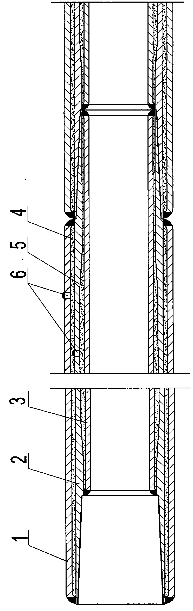
[0015] exist figure 1 In the shown embodiment: an outer pipe 1, an intermediate pipe 2 and an inner pipe 3 comprising a steel clearance suit, wherein one end of the intermediate pipe 2 is processed with an internal thread, and the other end is processed with an external thread, and one end of the intermediate pipe 2 is processed with an internal thread and an external thread. Pipe 1 is welded at the pipe end, and welded with inner pipe 3 at the reserved internal thread length, the end of the intermediate pipe 2 with external thread is welded with outer pipe 1 at the reserved external thread length, and with inner pipe 3 at the pipe end Welding; the annulus formed by the outer pipe 1 and the middle pipe 2 is filled with heat insulating material and evacuated to form the first heat insulation layer 4, and the annulus of the middle pipe 2 and the inner pipe 3 is evacuated...


PUM


Abstract

The invention relates to a heat-insulating oil sleeve. The heat-insulating oil sleeve is characterized by comprising an outer pipe, an intermediate pipe and an inner pipe which are sleeved in a clearance fit way; internal threads are machined at one end of the intermediate pipe; external threads are machined at the other end of the intermediate pipe; one end, provided with the internal threads, of the intermediate pipe is welded with the outer pipe at a pipe end, and is welded with the inner pipe at the length position of the preserved internal threads; one end, provided with the external threads, of the intermediate pipe is welded with the outer pipe at the length position of the preserved external threads, and is welded with the inner pipe at the pipe end; an annular cavity formed by the outer pipe and the intermediate pipe is filled with a heat-insulating material and is vacuumized to form a first heat-insulating layer; an annular cavity formed between the intermediate pipe and the inner pipe is vacuumized and is injected with inert gas to form a second heat-insulating layer. A manufacturing method for the heat-insulating oil sleeve comprises the following steps in sequence: performing pretreatment on the three pipes, sleeving and welding the inner pipe and the intermediate pipe, treating the annular cavity between the inner pipe and the intermediate pipe, sleeving and welding the outer pipe and the intermediate pipe, treating the annular cavity between the outer pipe and the intermediate pipe, testing an apparent heat conductivity coefficient and machining threads at the two ends of the intermediate pipe. The heat-insulating oil sleeve has a structure with three layers of steel tubes and double layers of heat-insulating layers, high heat insulation performance, long heat insulation life and high performance.

Description

technical field [0001] The invention relates to a method for manufacturing a heat-insulating oil casing, in particular to a steam injection and oil production tool for thermal recovery of heavy oil in the petroleum industry and its manufacturing method, belonging to the technical field of petroleum exploitation Background technique [0002] With the continuous development of the oil extraction industry and the continuous increase in oil consumption, the exploitation of heavy oil has become the main source of production for oil companies at home and abroad, and the exploitation of heavy oil usually adopts two processes: steam huff and puff and steam flooding, and these two processes Both require the use of heat-insulated oil pipes and casings as steam injection and oil recovery tools. The current heat-insulated oil pipes are all produced according to or with reference to a "vacuum heat-insulated oil pipe and its manufacturing process" disclosed in the Chinese patent (applicat...

Claims


Application Information

Patent Timeline
Patent Type & Authority Patents(China)
IPC IPC(8): E21B17/00E21B17/08B23P15/00
Inventor 宿行俊谢甲伟王新国李永志殷凤仕李文刚王加德于海龙
Owner 淄博孚瑞特热能科技有限公司
Why Eureka
Try Eureka