


Quick Research
Generate reliable direction feasibility study reports for your R&D in just a few steps.

Technical Q&A
Discover and master advanced knowledge NOW. Basics, ideas, possibilities, all at once.

Find Solutions
As an expert in R&D theories, this can generate solutions to your technical problems instantly.

Evaluate Feasibility
Analyze your overall solution with one click, know your potential R&D risks in advance.

Monitor Landscape
Get weekly tech updates, stay abreast of the latest tech innovations and key insights.
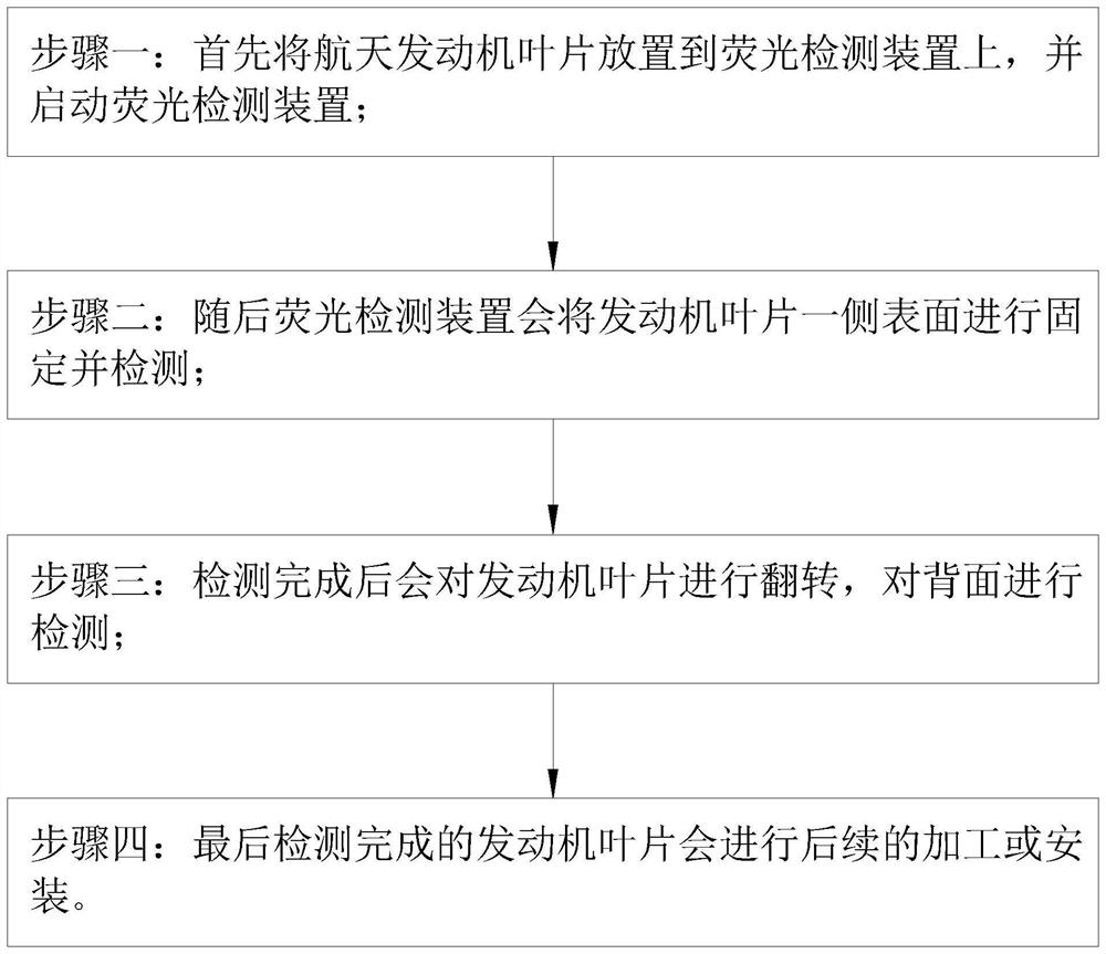
Fluorescent penetrant detection device for aero-engine blade and use method
A technology for aero-engines and engine blades, which is applied in the direction of optical testing for flaws/defects, etc. It can solve problems such as missed inspections or repeated inspections, easy to confuse, and affect normal inspections, so as to reduce the time for replacing windings, reduce workload, and avoid errors. The effect of the operation
- Summary
- Abstract
- Description
- Claims
- Application Information
AI Technical Summary
Problems solved by technology
Method used
Image


Examples
Embodiment Construction
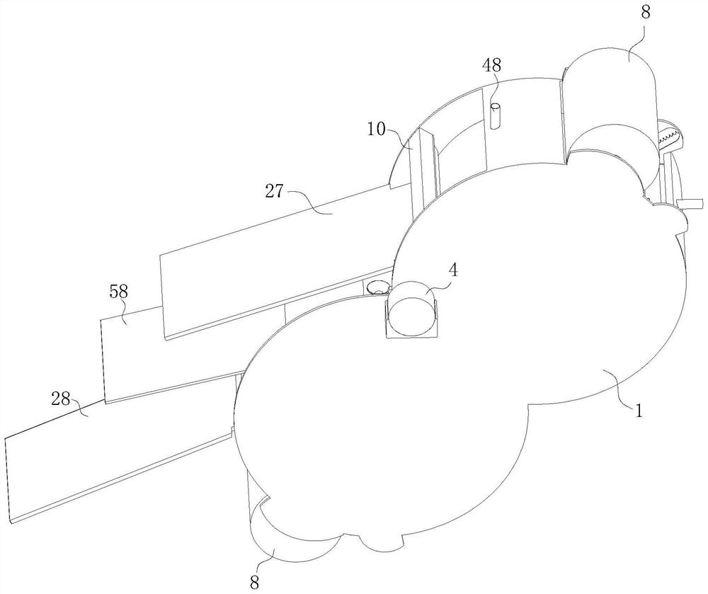
[0039] see Figure 1-14 , the present invention provides a technical solution: an aero-engine blade fluorescent penetration detection device, comprising a mounting shell 1, the inner wall of the mounting shell 1 is rotatably connected with a fixed cylinder 2, and one side end of the fixed cylinder 2 is fixedly connected with a first gear ring 3. A drive motor 4 is fixedly connected to the side surface of the mounting shell 1 close to the first gear ring 3 , and the end of the rotating shaft of the drive motor 4 penetrates the mounting shell 1 and is fixedly connected with a rotating gear 5 . The rotating gear 5 is connected to the first gear ring 3 . When engaged, the inner wall of the mounting shell 1 is sequentially provided with a sweeping brush 6, a first liquid spray box 7 capable of spraying the fluorescent agent, a wiping cotton 8 and a second liquid spray box capable of spraying the developer along the rotation direction of the fixed cylinder 2 9. A first detection end...
PUM
 Abstract
Description
Claims
Application Information
 - R&D Engineer
- R&D Manager
- IP Professional
- Industry Leading Data Capabilities
- Powerful AI technology
- Patent DNA Extraction
Browse by: Latest US Patents, China's latest patents, Technical Efficacy Thesaurus, Application Domain, Technology Topic, Popular Technical Reports.
© 2024 PatSnap. All rights reserved.Legal|Privacy policy|Modern Slavery Act Transparency Statement|Sitemap|About US| Contact US: help@patsnap.com