Generator for producing photon number state
A generation device and photon count technology, which can be applied to safety communication devices, optics, electromagnetic transmitters, etc., can solve the problems that multiple photons cannot be generated correctly, the timing of photons cannot be controlled, and the detector cannot detect the number of incident photons, etc.
- Summary
- Abstract
- Description
- Claims
- Application Information
AI Technical Summary
Problems solved by technology
Method used
Image
Examples
Embodiment 1
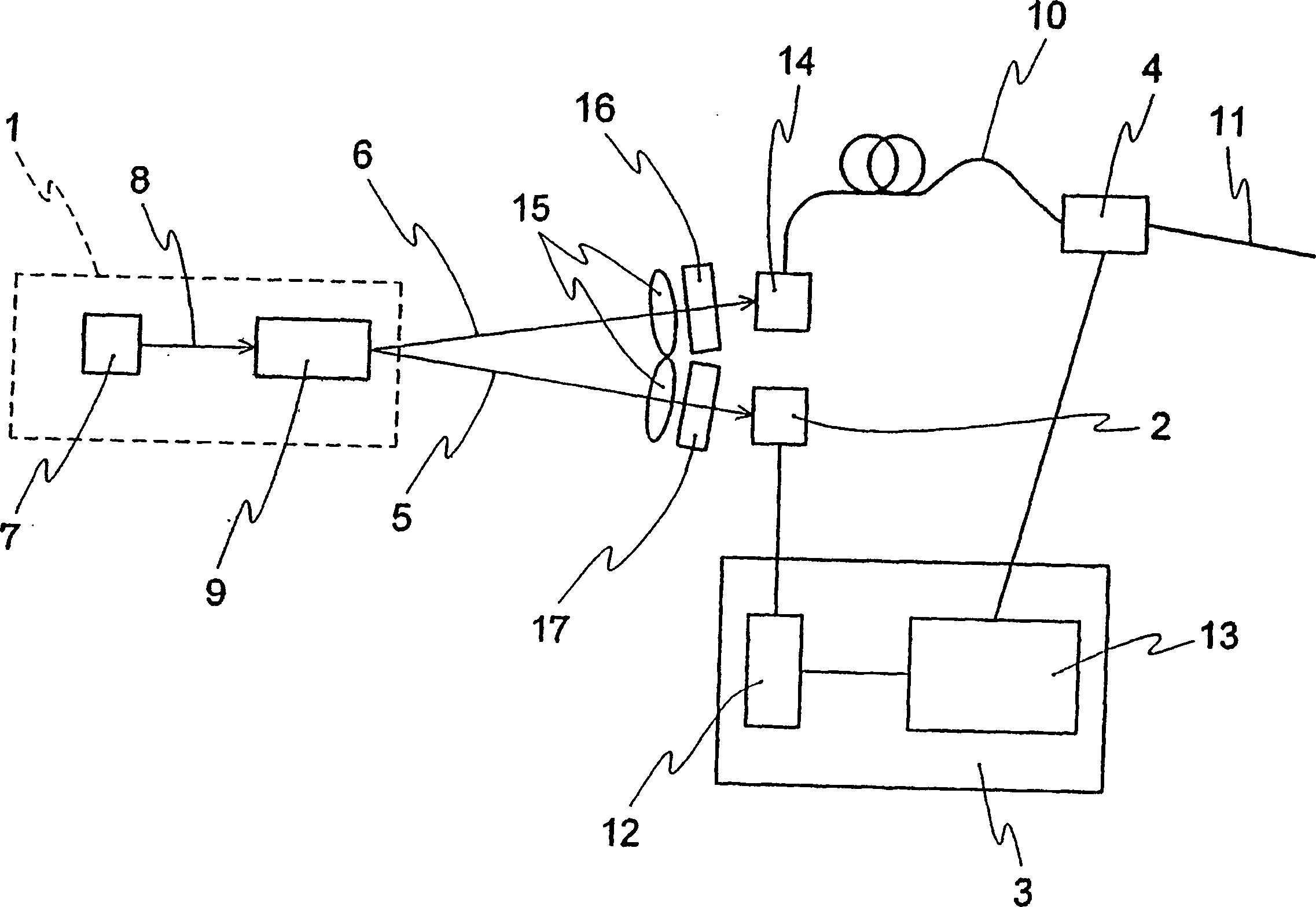
[0051] figure 1 is an overall structural diagram of an embodiment of the present invention. In this embodiment, it is a device that generates a single photon state in which two photons do not exist densely within the resolution time τ of the detector.
[0052] exist figure 1 Among them, 1 is a photon pair source that generates photon pairs that have a correlation relationship at the time of occurrence, 2 is a photon number detector that detects idle photons 5, and 3 is a control device that controls the gate device 4 according to the photon number information of the photon number detector . The gate device 4 controls the emission of signal photons 6 . Photon pair source 1 consists of a nonlinear optical medium 9 and a light source 7 of pumping light 8 pumping it. The idler photons 5 generated by the nonlinear optical medium 9 are focused onto the photon number detector 2 by the lens 15 through the optical filter 17 that selectively transmits the targeted idler photons. ...
Embodiment 2
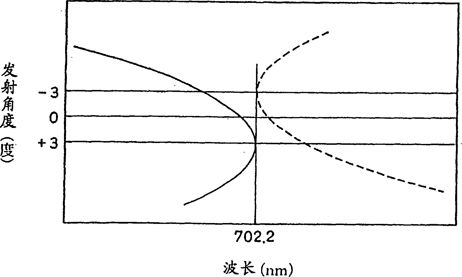
[0067] In Example 1, the wavelength of the generated signal light is 702.2 nm, however, this wavelength can be arbitrarily changed by selecting an appropriate pumping light source laser and nonlinear optical medium. For example, it can occur at wavelengths around 1550 nm, around 1310 nm, and around 800 nm, which are generally used in communications using optical fibers.
[0068] Example 1 ( figure 2 The generation method of photon pairs shown in ) is suitable for obtaining photon pair beams with equal wavelength and small angular spread. However, for other purposes, photons with different wavelengths can also be obtained by changing the direction of the optical axis of the BBO crystal. right. At this time, figure 2 The two resonance curves are respectively tangent to the straight lines corresponding to different wavelengths. At this time, the extraction direction of the photon is given by figure 2 The resonance curves shown are taken at angles tangent to the straight li...
Embodiment 3
[0072] Other embodiments of the invention are shown in Figure 5 . In this embodiment, 7 is the pumping light source, 18 is the optical fiber that guides the pumping light, 19 is the waveguide nonlinear medium, and 20 is the fluorescence pair and the pumping light generated from the waveguide nonlinear optical medium 19. A waveguide filter for light, 21 is an exit port for pumping light, and 22 is a waveguide filter for dividing the fluorescent pair into two branches.
[0073] In this embodiment, the parametric fluorescence pair occurs in the waveguide type nonlinear optical medium 19 . Fluorescence pairs have longitudinal and transverse polarizations respectively, and in waveguide filter 22 operating as a polarized beam splitter, fluorescence having one of the polarizations is transmitted to the photon number detector, and the other is transmitted to the photon number detector. to fiber 10.
[0074] With such a structure, the device can be miniaturized, and optical adjustme...
PUM
 Abstract
Description
Claims
Application Information
 - R&D
- Intellectual Property
- Life Sciences
- Materials
- Tech Scout
- Unparalleled Data Quality
- Higher Quality Content
- 60% Fewer Hallucinations
Browse by: Latest US Patents, China's latest patents, Technical Efficacy Thesaurus, Application Domain, Technology Topic, Popular Technical Reports.
© 2025 PatSnap. All rights reserved.Legal|Privacy policy|Modern Slavery Act Transparency Statement|Sitemap|About US| Contact US: help@patsnap.com


