High-speed rail transit brake part casting structure and manufacturing process thereof

A technology of high-speed rails and brake parts, which is applied in the direction of manufacturing tools, casting molds, and casting mold components. It can solve problems such as defective products, eccentric cores, and inconvenient demoulding and picking up parts, so as to maintain stability and speed up flow effect

Pending Publication Date: 2022-08-05
CHANGZHOU INST OF TECH
View PDF1 Cites 0 Cited by
  • Summary
  • Abstract
  • Description
  • Claims
  • Application Information

AI Technical Summary

Problems solved by technology

[0004] However, in the above casting mold structure, the sand core used to form the middle through hole is generally only positioned with the upper box or the lower box. During the casting process, the position of the sand core will easily cause eccentricity, resulting in defective products. It is inconvenient to take out molded parts, manual assistance is required, and the demoulding effect is poor

Method used


Image

  • High-speed rail transit brake part casting structure and manufacturing process thereof
  • High-speed rail transit brake part casting structure and manufacturing process thereof
  • High-speed rail transit brake part casting structure and manufacturing process thereof

Examples


Embodiment 1

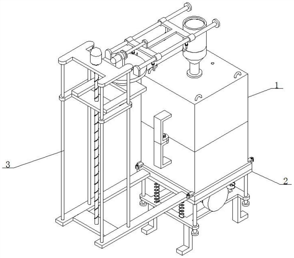
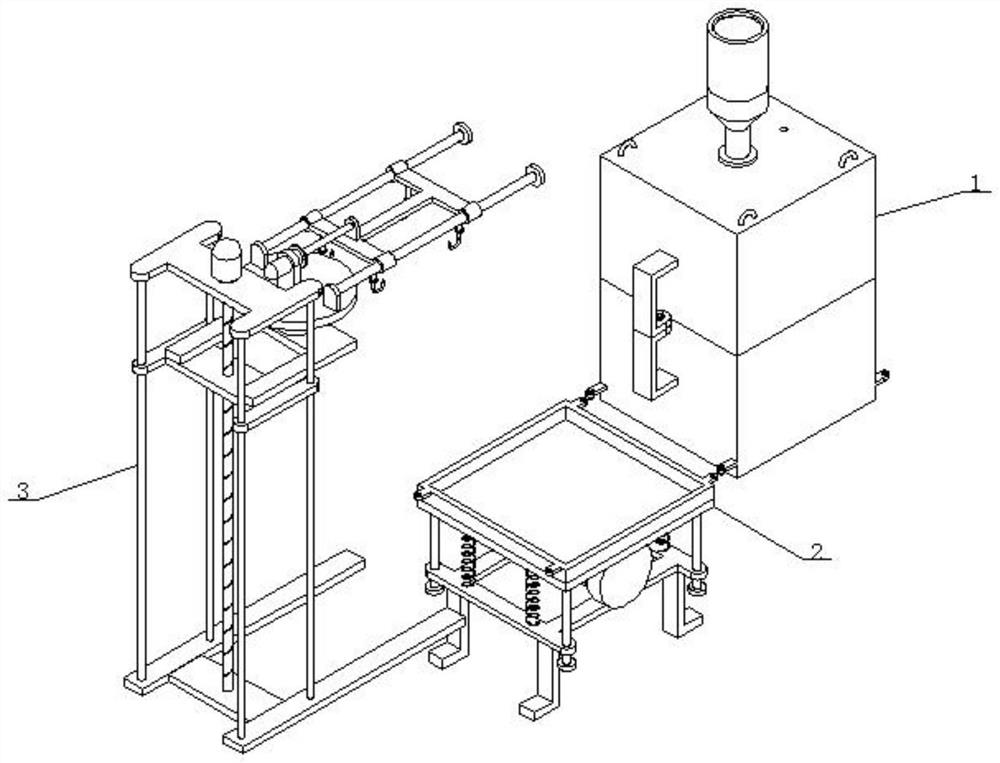
[0046] See figure 1 As well as figure 2 As well as image 3 As well as Figure 4 As well as Figure 5 As well as Image 6 As well as Figure 7 As well as Figure 8 and Figure 9 It shows, a high -speed rail transit braking parts casting structure, including casting components for pouring for molding high -speed rail transit parts 1. Support component 2 and raising component 3; The assembly of the mold and the production of the cavity, and then use the support component 2 to support the support of the cast component 1, while generating vibration, which is convenient for the metal solution to enter, and facilitates the release of the formation in the later stage. Component 1 performs a combination and release.

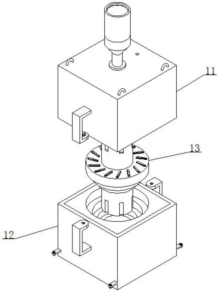
[0047] Casting component 1 includes the upper box 11 and the lower box 12, of which the upper box 11 and the lower box 12 are filled with the first sand core 14 and the second sand core 15, and the first sand core 14 and the second sand core 15 are poured. There are 13 castings for...

Embodiment 2

[0061] The device provided by the present invention, the principle and the technical effects generated by the implementation of the same examples and the implementation example 1 are the same. To briefly describe, the example of the embodiments can be referred to the corresponding content in the Example 1.

[0062] Step 8: Put a certain amount of scrap steel into the mid -frequency electric furnace to melt into steel water, and when the temperature in the medium frequency electric furnace rises to 1040 ° C, then put it into steel ingots, raw iron, and return furnaces, and then scum. When the temperature in the Chinese frequency electric furnace rises to 1380 ° C, the iron is released. At this time, a certain amount of copper and molybdenum are poured with the iron water. In the 5th minute of pouring, the ultrasonic treatment is used for 3 minutes. After 15 minutes of pouring The weight percentage of the chemical components of the brakes casting, the percentage of the chemical comp...


PUM


Abstract

The invention discloses a high-speed rail transit brake part casting mold structure and a manufacturing process thereof, and the high-speed rail transit brake part casting mold structure comprises a casting mold assembly for casting and forming a high-speed rail transit brake part, a supporting assembly and a material lifting assembly. According to the casting mold structure, the problems that in an existing casting mold structure, a sand core used for forming a middle through hole is generally only positioned with an upper box or a lower box, in the casting process, core shift is easily caused by position change of the sand core, accordingly, defective products are generated, meanwhile, demolding and part taking in the later period are inconvenient, manual assistance is needed, and the demolding treatment effect is poor are solved.

Description

Technical field [0001] The present invention involves the field of high -speed rail transit braking parts, and especially involves a high -speed rail transit braking parts casting structure and its manufacturing process. Background technique [0002] The urban high -speed rail transit system refers to the transportation system that uses vehicles to run on a fixed guide rail and mainly used for urban passenger transport in the city. The brake parts as an important accessories for urban high -speed rail transit. For the service life, most of the existing urban high -speed rail transit braking parts are mostly used for casting. [0003] The open number is CN201810299936.7, the name is a cast and smelting modeling machine, including the model of the modeling machine, which has a base at the bottom of the model of the model. The bottom end runs through the tank and extends to the inside of the base, and the bottom surface of the model's body is fixed to the sliding rail. The hinge has...

Claims


Application Information

Patent Timeline
IPC IPC(8): B22C9/02B22C21/00B22C9/10B22C9/08B22D27/08B22D29/04B22D33/04B22D33/06B22C21/10C22C37/08C22C37/10
CPCB22C9/02B22C21/00B22C9/10B22C9/108B22C9/082B22D27/08B22D29/04B22D33/04B22D33/06B22C21/10C22C37/08C22C37/10
Inventor 曹霞徐吉江炜龙兵高双胜白建会李春娟
Owner CHANGZHOU INST OF TECH
Why Eureka
Try Eureka