
Zero-current-loss single-tube grid-control circuit with pre-voltage-stabilization function

A pre-regulated, zero-current technology, applied in the direction of regulating electrical variables, control/regulating systems, instruments, etc., can solve the problems of increasing chip area, increasing design difficulty, and large current loss, and achieves miniaturization of chip area and good pre-conditioning. Voltage stabilization effect, circuit minimization effect

Active Publication Date: 2022-07-29
XIDIAN UNIV
View PDF7 Cites 0 Cited by
  • Summary
  • Abstract
  • Description
  • Claims
  • Application Information

AI Technical Summary

Problems solved by technology

However, the process inevitably involves loop stability design, which requires capacitance compensation, which not only increases the design difficulty, but also increases the additional chip area. Compared with the floating ground technology, the current branches consumed by these two technologies are much larger. more, more current loss

Method used


Image

  • Zero-current-loss single-tube grid-control circuit with pre-voltage-stabilization function
  • Zero-current-loss single-tube grid-control circuit with pre-voltage-stabilization function
  • Zero-current-loss single-tube grid-control circuit with pre-voltage-stabilization function

Examples


Embodiment 1

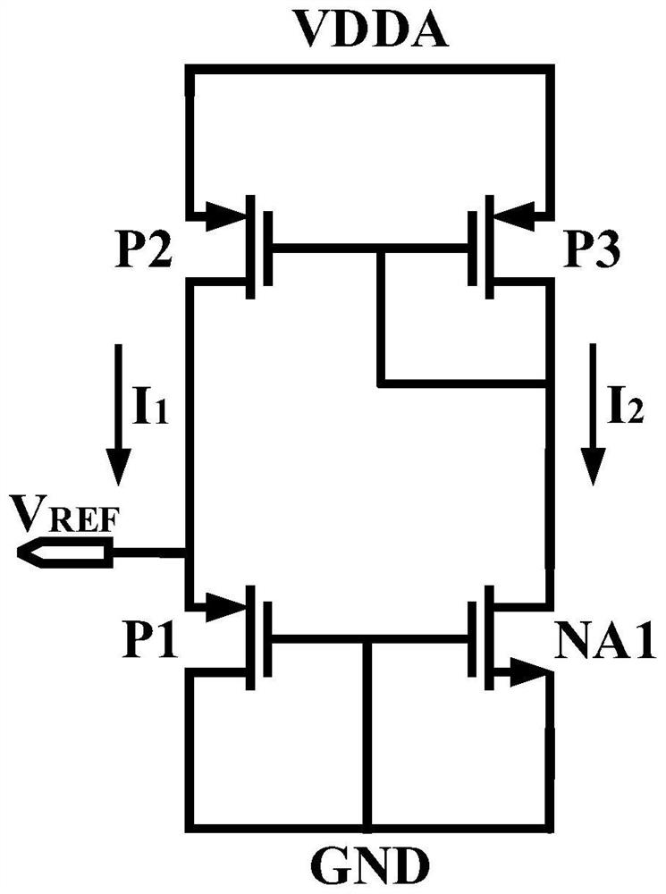
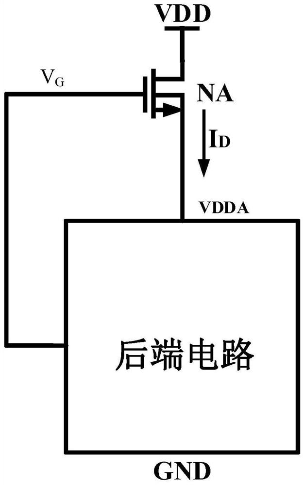
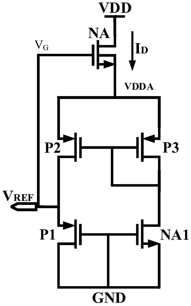
[0037] A pre-regulated zero-current loss single-tube gate control circuit comprises: a back-end circuit and a MOSFET device electrically connected with the back-end circuit. The threshold voltage of the MOSFET device is zero limit or the MOSFET device is depletion mode. The gate voltage control of the MOSFET device is used for pre-regulation to provide a pre-regulation potential for the back-end circuit. where the zero limit is a positive or negative value equal to or close to 0. The back-end circuit is the part of the circuit that requires pre-regulated power supply.

[0038] In this embodiment, only one MOSFET device or depletion-mode MOSFET device with a threshold voltage of zero limit can be used to realize pre-regulation, and the positive gate voltage control and the back-gate voltage control are respectively used to realize pre-regulation. The pre-regulation part No additional current branch is introduced, and the current consumed on it is the inherent current loss of ...

Embodiment 2

[0040] On the basis of the first embodiment, the MOSFET device is an N-type MOSFET device (NMOS device). Among them, for an N-type MOSFET device, the threshold voltage is zero limit value, that is, the threshold voltage is a positive value equal to 0 or close to 0, or the MOSFET device is a depletion-type N-type MOSFET device with a negative threshold voltage. .

[0041] Using the gate voltage control of the MOSFET device to perform pre-regulation to provide a pre-regulated potential for the back-end circuit, including: using the gate voltage control of the MOSFET device to pre-regulate the power supply voltage to provide a pre-regulated input potential for the back-end circuit. In this embodiment, the N-type MOSFET device can be controlled by a positive gate voltage and a back gate (substrate) voltage, respectively.

[0042] Among them, single-transistor positive gate control pre-regulation refers to: using a single N-type MOSFET device with a threshold voltage equal to 0 or...

Embodiment 3

[0069] On the basis of the first embodiment, the MOSFET device is a P-type MOSFET device (PMOS device). The threshold voltage of a P-type MOSFET device is zero limit or positive. Among them, for P-type MOSFET devices, the zero limit is 0 or a negative value close to 0, that is, a P-type Native MOSFET device with a threshold voltage of 0 or a negative value close to zero, or a power consumption with a positive threshold voltage. Exhaust-type PMOS devices are used as P-type MOSFET devices. Using the gate voltage control of the MOSFET device to perform pre-regulation to provide a pre-regulated potential for the back-end circuit, including: using the gate voltage control of the MOSFET device to pre-regulate the ground potential to provide the back-end circuit with a pre-regulated ground potential.

[0070] The realization of pre-regulation is described in detail below with depletion-mode PMOS devices: the back-end circuit is the part of the circuit that needs pre-regulated power ...


PUM


Abstract

The invention discloses a pre-voltage-stabilizing zero-current-loss single-tube grid-control circuit. The pre-voltage-stabilizing zero-current-loss single-tube grid-control circuit comprises a rear-end circuit and an MOSFET (Metal-Oxide-Semiconductor Field Effect Transistor) device electrically connected with the rear-end circuit, the threshold voltage of the MOSFET device is a zero limit value; and the gate voltage control of the MOSFET device is adopted to carry out pre-voltage stabilization so as to provide a pre-voltage-stabilization potential for the rear-end circuit. Pre-voltage stabilization can be achieved only through an MOSFET device with the threshold voltage being the zero limit value or a depletion type MOSFET device, positive gate voltage control and back gate voltage control are used for achieving pre-voltage stabilization, an extra current branch is not introduced into the pre-voltage-stabilization part, current consumed by the pre-voltage-stabilization part is inherent current loss of a system, and therefore the current consumption of the pre-voltage-stabilization part is reduced. Extra current loss is avoided, the PSRR characteristic of the reference voltage is greatly improved, and a good pre-voltage-stabilizing effect is achieved; the minimization of the circuit and the minimization of the chip area are realized by a single device; the method does not involve the stability problem, is simpler in design and wider in application range, and can be applied to the fields of high-voltage pre-voltage-stabilizing integrated circuit design and the like.

Description

technical field [0001] The invention belongs to the technical field of analog integrated circuits, and in particular relates to a pre-regulated zero current loss single-tube gate control circuit. Background technique [0002] With the current development of integrated circuits, higher requirements are put forward for the performance of products in all aspects, especially in the field of integrated circuits such as reference voltage, reference current, and high-voltage pre-regulation that pre-regulate the power supply voltage. Among them, chips in the reference voltage and reference current fields need pre-regulation to improve the PSRR characteristics and linear adjustment rate characteristics of the output reference, and high-voltage application chips need pre-regulation to protect the internal circuit from high voltage breakdown. At present, the overall development direction of pre-regulation technology is low voltage, low power consumption, high efficiency, high precision...

Claims


Application Information

Patent Timeline
IPC IPC(8): G05F3/26
CPCG05F3/26
Inventor 柴常春陈柯旭宋博奇李福星秦英朔孟祥瑞
Owner XIDIAN UNIV
Learn More