Complete set of controllable shearing-resistant and pulling-resistant connecting piece for detachable steel-concrete composite beam bridge and construction method of complete set of controllable shearing-resistant and pulling-resistant connecting piece
A connecting piece and a complete set of technology, applied in bridge parts, bridges, bridge construction, etc., can solve problems such as inaccurate control and calculation, and affect the overall mechanical performance, so as to achieve assembly and rapid construction, reliable construction quality, Improved long-term performance and durability effects
- Summary
- Abstract
- Description
- Claims
- Application Information
AI Technical Summary
Problems solved by technology
Method used
Image
Examples
Embodiment 1
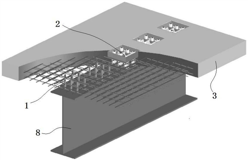
[0042] see figure 1 , the present embodiment discloses a complete set of controllable shear-resistant and pull-resistant connectors for a detachable steel-concrete composite girder bridge, including a plurality of bolts 1 and a plurality of embedded parts 2 .
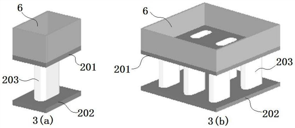
[0043] The embedded part 2 includes an upper steel plate 201, a lower steel plate 202 and a steel pipe 203, and the cross-section of the steel pipe 203 is a straight-sided ellipse.
[0044] see image 3 , the upper steel plate 201 and the lower steel plate 202 are arranged horizontally, the upper steel plate 201 is located directly above the lower steel plate 202 , and one or more vertical steel pipes 203 are welded between the upper steel plate 201 and the lower steel plate 202 . image 3 Shown in a is a structure in which a steel pipe 203 is welded between the upper steel plate 201 and the lower steel plate 202, image 3 b shows a structure in which a plurality of steel pipes 203 are welded between the upper steel p...
Embodiment 2
[0056] This embodiment discloses a construction method for a complete set of controllable shear-resistant and pull-resistant connectors for a detachable steel-concrete composite girder bridge described in Embodiment 1, including the following steps:
[0057] 1) Connect a plurality of said bolts 1 to the steel beam 8.
[0058] 2) The embedded parts 2 are embedded in the precast concrete bridge deck 3 , and the edge sealing plate 6 is welded on the upper surface of the upper steel plate 201 .
[0059] 3) Passing a plurality of the bolts 1 through the corresponding embedded parts 2 respectively.
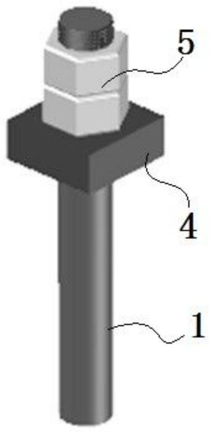
[0060] 4) Install the steel backing plate 4 on the bolt 1 and tighten the nut structure 5, and perform spot welding on the nut structure 5 and the bolt 1.
[0061] 5) Fill the groove 301 with elastic material, and install the movable steel cover 7 at the opening of the groove 301 .
Embodiment 3
[0063] see figure 1 , the present embodiment discloses a complete set of controllable shear-resistant and pull-resistant connectors for a detachable steel-concrete composite girder bridge, including a plurality of bolts 1 and a plurality of embedded parts 2 .
[0064] The embedded part 2 includes an upper steel plate 201, a lower steel plate 202 and a steel pipe 203, and the cross-section of the steel pipe 203 is a straight-sided ellipse.
[0065] see image 3 , the upper steel plate 201 and the lower steel plate 202 are arranged horizontally, the upper steel plate 201 is located directly above the lower steel plate 202 , and one or more vertical steel pipes 203 are welded between the upper steel plate 201 and the lower steel plate 202 . image 3 Shown in a is a structure in which a steel pipe 203 is welded between the upper steel plate 201 and the lower steel plate 202, image 3 b shows a structure in which a plurality of steel pipes 203 are welded between the upper steel p...
PUM
 Abstract
Description
Claims
Application Information
 - R&D Engineer
- R&D Manager
- IP Professional
- Industry Leading Data Capabilities
- Powerful AI technology
- Patent DNA Extraction
Browse by: Latest US Patents, China's latest patents, Technical Efficacy Thesaurus, Application Domain, Technology Topic, Popular Technical Reports.
© 2024 PatSnap. All rights reserved.Legal|Privacy policy|Modern Slavery Act Transparency Statement|Sitemap|About US| Contact US: help@patsnap.com


