Vacuum insulator, method of manufacturing the same and refrigerator having the same
A technology for vacuum insulation and refrigerator, which is applied to separation methods, household refrigerators, chemical instruments and methods, etc. The effect of improving short-term performance, improving initial performance, improving long-term performance
- Summary
- Abstract
- Description
- Claims
- Application Information
AI Technical Summary
Problems solved by technology
Method used
Image
Examples
no. 1 approach
[0059]
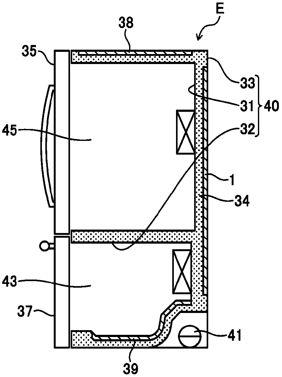
[0060] figure 1 A cross-sectional view illustrating a configuration of a refrigerator E according to various embodiments of the present disclosure.
[0061] like figure 1 As shown, the refrigerator E according to the present embodiment includes an outer case 33 and inner cases 32 and 31 received in the outer case 33 and forming storage compartments in the outer case 33 , respectively. Both the inner cases 32 and 31 and the outer case 33 have openings formed in the forward direction. exist figure 1 In the example shown, the storage compartment in the inner shell 32 is a freezer compartment 43 set to be at a freezing temperature, and the storage compartment in the inner shell 31 is a refrigerated compartment 45 set to be at a refrigerated temperature.
[0062] The vacuum heat insulator 1 on the rear surface of the refrigerator E is provided between the inner cases 32 and 31 and the outer case 33, and the vacuum heat insulator 38 on the top surface of the refrigerat...
no. 2 approach
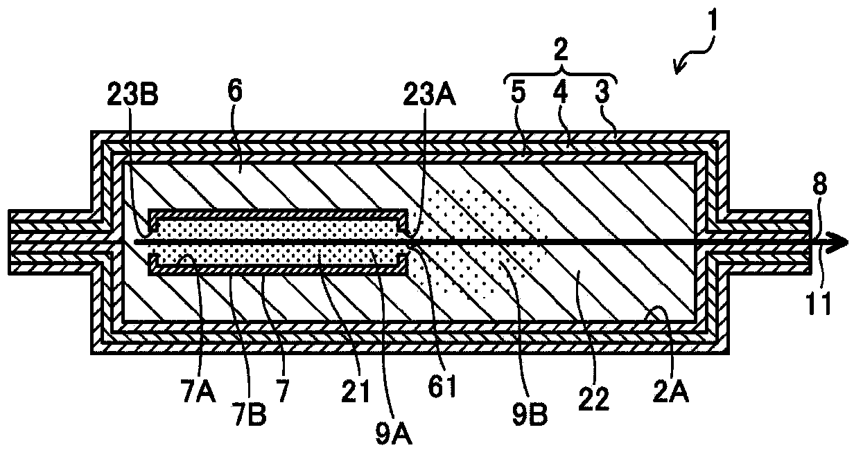
[0116] Figure 5 A cross-sectional view showing a configuration of a vacuum heat insulator according to various embodiments of the present disclosure.
[0117] In the vacuum heat insulating material 1 according to the above embodiment, the container 7 includes the two openings 23A and 23B, but as Figure 5 As shown, only one opening 23 may be formed. Furthermore, the location where the opening 23 is to be formed is not limited to the discharge port 8 of the outer envelope 2 , and the opening 23 may be formed in any surface of the container 7 . Specifically, for example, as Image 6 As shown, the opening 23 is formed in the surface 72 of the container 7, and as Figure 5 As shown, the opening 23 may be installed such that the opening direction of the opening 23 is perpendicular to the suction direction of the evacuation.
[0118] According to this configuration, since only one opening 23 is formed, the operability of processes S2 and S4 can be improved. In addition, because ...
no. 3 approach
[0120] In the first and second embodiments, two openings 23 or one opening 23 are formed, but three or more (ie, plural) openings may be formed. Specifically, for example, a plurality of small openings each having a maximum diameter of about 3 mm may be formed. Therefore, in the process S4, when the container 7 is installed in the outer envelope 2, the adsorbent 9 is not easy to overflow from the inside of the container 7, thereby improving workability.
[0121] Regardless of the embodiment of the opening 23, the ratio of the area of the opening 23 to the total surface area of the outer surface 7B of the container 7 (hereinafter, referred to as "area ratio") is preferably 2 to 40%, more specifically 3 to 40%. 30%, and especially preferably 4 to 20%. Therefore, the ratio of the adsorbent 9A and the adsorbent 9B can be adjusted, thereby improving the short-term and long-term performance of the adsorbent 9 .
[0122] With this configuration, the adsorbent 9B only needs to d...
PUM
| Property | Measurement | Unit |
|---|---|---|
| diameter | aaaaa | aaaaa |
| particle size | aaaaa | aaaaa |
| particle size | aaaaa | aaaaa |
Abstract
Description
Claims
Application Information
 - Generate Ideas
- Intellectual Property
- Life Sciences
- Materials
- Tech Scout
- Unparalleled Data Quality
- Higher Quality Content
- 60% Fewer Hallucinations
Browse by: Latest US Patents, China's latest patents, Technical Efficacy Thesaurus, Application Domain, Technology Topic, Popular Technical Reports.
© 2025 PatSnap. All rights reserved.Legal|Privacy policy|Modern Slavery Act Transparency Statement|Sitemap|About US| Contact US: help@patsnap.com


