


Quick Research
Generate reliable direction feasibility study reports for your R&D in just a few steps.

Technical Q&A
Discover and master advanced knowledge NOW. Basics, ideas, possibilities, all at once.

Find Solutions
As an expert in R&D theories, this can generate solutions to your technical problems instantly.

Evaluate Feasibility
Analyze your overall solution with one click, know your potential R&D risks in advance.

Monitor Landscape
Get weekly tech updates, stay abreast of the latest tech innovations and key insights.
Cylindrical synchronous reluctance linear motor
A linear motor and synchronous reluctance technology, which is applied in the direction of electromechanical devices, electrical components, electric components, etc., can solve the problems of low utilization rate of windings, large torque ripple of synchronous reluctance motors, and high cost of permanent magnet linear motors
- Summary
- Abstract
- Description
- Claims
- Application Information
AI Technical Summary
Problems solved by technology
Method used
Image


Examples
Embodiment 1
[0032] This embodiment provides a cylindrical synchronous reluctance linear motor.
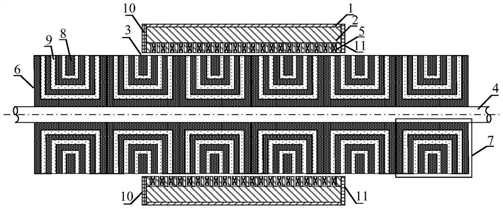
[0033] A cylindrical synchronous reluctance linear motor, comprising: a casing, an armature iron core, a magnetic barrier body, a magnetic barrier and a shaft, wherein the armature iron core is provided with a slot along the vertical direction of the shaft and an armature winding is placed in the slot. Structural body, the magnetic barrier is a structure composed of a plurality of magnetic barriers, and an air gap is set between the magnetic barrier and the armature core; wherein, the magnetic barrier comprises magnetically conductive materials arranged in a regular distribution and non-magnetic materials;
[0034] During use, the armature iron core and the magnetic barrier body perform reciprocating relative movement along the axial direction; the reciprocating relative movement is realized by connecting the casing and the shaft with the outside world to maintain a fixed position.
[0035] A...
Embodiment approach
[0039] As one or more embodiments, the armature core 2 is provided with a certain number of stator slots in the axial direction, and the armature windings 5 are arranged in the stator slots.
[0040] In this embodiment, the casing 1 and the armature core 2 are fixedly connected or integrally arranged, and the shaft 4 is fixedly connected or integrally arranged with the magnetic barrier 5 .
[0041] In this embodiment, the left end cover 10 and the right end cover 11 are fixedly connected to or integrated with the casing 1 .
[0042]As one or more embodiments, the casing 1 adopts a non-magnetic conductive material.
[0043] In this embodiment, the axial length of the armature core 2 is smaller than the axial length of the magnetic barrier 5 .
[0044] In this embodiment, reciprocating relative motion can be performed between the armature core 2 and the magnetic barrier 5 along the axial direction;
[0045] As one or more implementations, the relative movement is achieved by...
Embodiment 2
[0048] This embodiment provides a cylindrical synchronous reluctance linear motor.
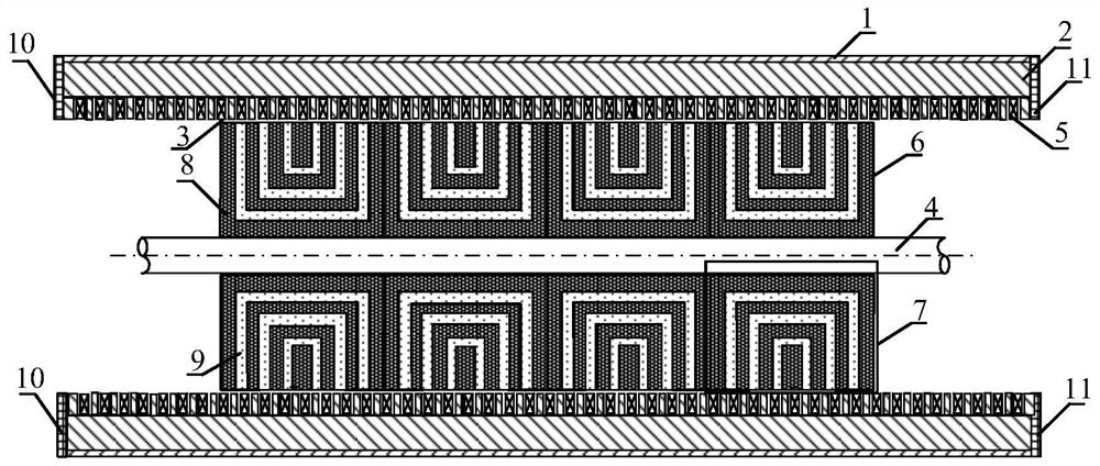
[0049] The difference between this embodiment and the first embodiment is that the length of the armature core along the axial direction is greater than the length of the magnetic barrier body along the axial direction.
[0050] like image 3 As shown, the magnetic barrier built-in cylindrical synchronous reluctance linear motor of this embodiment includes a magnetic barrier 7, specifically, a magnetically permeable material 8 and a non-magnetically permeable material 9; the magnetically permeable material 8 and the non-magnetically permeable material 9 The materials 9 are regularly distributed and arranged to form a cylindrical magnetic barrier.
[0051] In this embodiment, the armature core 2 is arranged in the casing 1 , the magnetic barrier 7 is combined into a magnetic barrier 5 , and the shaft 4 is arranged inside the magnetic barrier 5 .
[0052] In this embodiment, an air gap is set ...
PUM
 Abstract
Description
Claims
Application Information
 - R&D Engineer
- R&D Manager
- IP Professional
- Industry Leading Data Capabilities
- Powerful AI technology
- Patent DNA Extraction
Browse by: Latest US Patents, China's latest patents, Technical Efficacy Thesaurus, Application Domain, Technology Topic, Popular Technical Reports.
© 2024 PatSnap. All rights reserved.Legal|Privacy policy|Modern Slavery Act Transparency Statement|Sitemap|About US| Contact US: help@patsnap.com