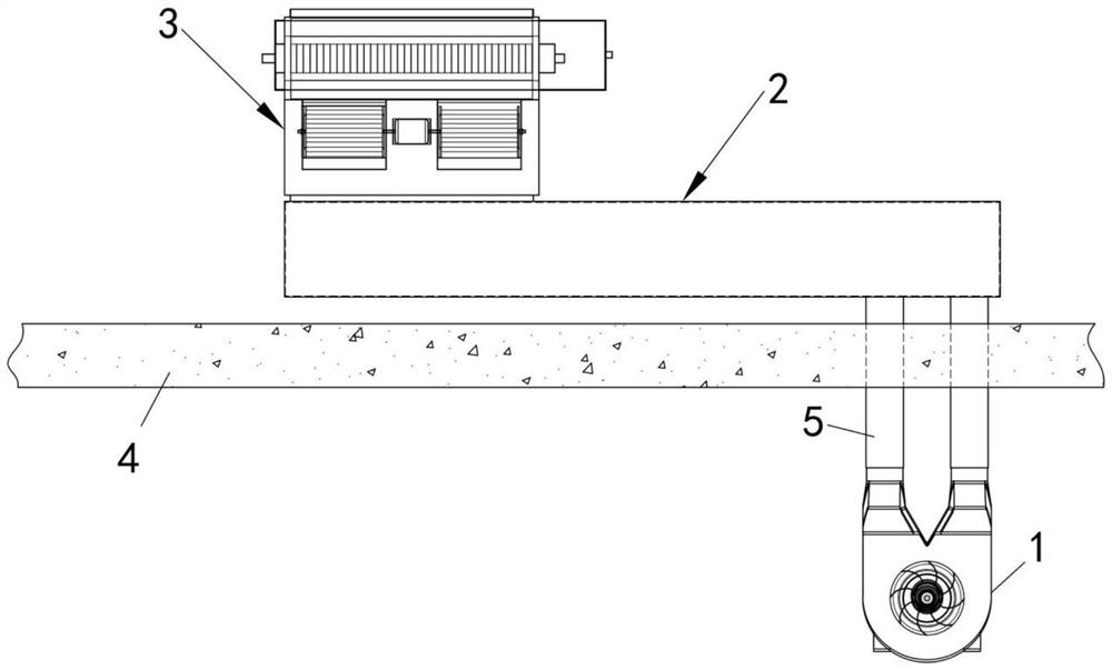
Combined fresh air module
A combined, fresh air technology, used in ventilation systems, heating methods, space heating and ventilation, etc., can solve problems such as room temperature and humidity fluctuations, secondary pollution, and fresh air not coming in, saving equipment resources and ensuring stability. Sex, the effect of removing the vortex
- Summary
- Abstract
- Description
- Claims
- Application Information
AI Technical Summary
Problems solved by technology
Method used
Image
Examples
Embodiment 1
[0051] Please refer to Figure 3 to Figure 6 , a combined fresh air module, applied to a group of rooms in a building, which includes a front air inlet device 1, a header 2 and a room fan coil unit 3 connected in sequence, and the header 2 is a hollow structure, such as a header 2. The body can be made of 1.2-1.5mm cold-rolled sheet or aluminum sheet after punching, bending and riveting, and then riveting with two end caps. Of course, this embodiment is not limited to cold-rolled sheet and aluminum sheet, but can also be pipes made of other materials. Since the header 2 is used to communicate the front air inlet device 1 and the room fan coil unit 3 , the header 2 is provided with an air inlet and an air outlet.
[0052] The front air inlet device 1 includes a casing and an air inlet fan, the casing is provided with a fresh air outlet, an air outlet and an air inlet channel connecting the fresh air outlet and the air outlet, and the air inlet fan is arranged at the In the air...
Embodiment 2
[0060] Header 2 is the core component of the combined fresh air module. It not only provides fresh air passages, but also decelerates and reduces noise in the header 2, changing from turbulent flow to laminar flow, preventing the fresh air flow from affecting the room fan in the form of high-speed jet turbulence. The fan impeller in the return air box 32 of the coil 3 produces impact and even disrupts the dynamic balance of the fan impeller, so that the fresh air flows into the return air box 32 of the room fan coil 3 in a low-speed laminar flow pattern of ≤3m / s.
[0061] This embodiment is further improved on the basis of Embodiment 1. Please refer to Figure 7 to Figure 10 In this embodiment, in order to effectively realize the above-mentioned function of “fresh air flow deceleration and noise reduction, from turbulent flow to laminar flow” of the header 2, an air distribution orifice plate 6 is arranged in the inner cavity of the header 2, and the air distribution orifice p...
Embodiment 3
[0063] This embodiment is further improved on the basis of Embodiment 2. The header 2 in the embodiment 1 is a long strip structure, the air ducts in the header 2 are arranged along the length direction of the header 2, and the air inlet of the header 2 communicated with the air duct in the header 2 is connected to the air inlet of the header 2. The air outlets are arranged in the length direction of the header 2, on both sides of the header 2 and staggered, that is, the room fan coil 3 and the front air inlet device 1 are also staggered and not on the same straight line.
[0064] Please refer to Figure 11 and Figure 12 , in this embodiment, the length of the header 2 is shortened, so that the air inlet of the header 2 is directly opposite to the air outlet, that is, the room fan coil 3 and the front air inlet device 1 are opposite (directly opposite), in the same in a straight line. The fresh air flow of the front air inlet device 1 has the characteristics of jet flow, a...
PUM
 Abstract
Description
Claims
Application Information
 - R&D
- Intellectual Property
- Life Sciences
- Materials
- Tech Scout
- Unparalleled Data Quality
- Higher Quality Content
- 60% Fewer Hallucinations
Browse by: Latest US Patents, China's latest patents, Technical Efficacy Thesaurus, Application Domain, Technology Topic, Popular Technical Reports.
© 2025 PatSnap. All rights reserved.Legal|Privacy policy|Modern Slavery Act Transparency Statement|Sitemap|About US| Contact US: help@patsnap.com


