Smoke exhaust device with smoke guide plate and lighting device

A lighting device and oil fume extraction technology, which is applied in the direction of oil fume removal, lighting and heating equipment, household appliances, etc., can solve the problem of expensive structure, and achieve the effects of simplified installation, simplified overall structure, and uniform light output

Pending Publication Date: 2022-07-08
BSH BOSCH & SIEMENS HAUSGERAETE GMBH
View PDF1 Cites 0 Cited by
  • Summary
  • Abstract
  • Description
  • Claims
  • Application Information

AI Technical Summary

Problems solved by technology

[0003] The disadvantage of this extractor hood is that the construction is expensive
Due to the reflector and the diffuser comprising light-scattering and light-trapping elements, this configuration is moreover subject to high losses

Method used


Image

  • Smoke exhaust device with smoke guide plate and lighting device
  • Smoke exhaust device with smoke guide plate and lighting device
  • Smoke exhaust device with smoke guide plate and lighting device

Examples


Embodiment Construction

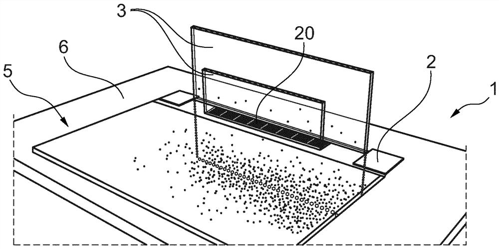
[0038] exist figure 1 A perspective view of an embodiment of the cooker hood 1 according to the invention is shown in FIG. The cooker hood 1 is arranged behind the cooktop 5 in the work panel 6 . The range hood device 1 has a range hood housing 2 in which the range hood is figure 1 Only the upper side can be seen. In the cooking fume housing 2, a suction opening 20 is provided in the upper side. Through this suction port 20 , steam and smoke generated during cooking on the cooktop 5 can be sucked into the cooker hood 1 . For this purpose, the extractor hood 1 has a blower, which is not shown in the drawings.

[0039] exist figure 1 In the illustrated embodiment, the cooker fume device 1 has two fume guide plates 3 . In particular, in front of the suction opening 20 , that is to say between the suction opening 30 and the cooktop 5 and behind the suction opening 20 , a fume guide plate 3 is respectively arranged. The smoke guide plate 3 is in the vertical line and represe...


PUM


Abstract

The invention relates to a fume extraction device having at least one fume guide plate (3) and at least one lighting device (4). The fume extraction device (1) is characterized in that the fume guide plate (3) represents an optical waveguide, the lighting device (4) comprises a housing (40) for at least one light source (430), the housing is at least partially made of a transparent material, at least one part of the lighting device (4) made of a transparent material faces the fume guide plate (3), and the light source (430) is arranged in the housing (40). At least one part of the smoke guide plate (3) facing the edge (30) of the lighting device (4) has the characteristic of light scattering.

Description

technical field [0001] The invention relates to a range fume device with a fume guide plate and a lighting device. Background technique [0002] For cooker hoods, it is known to produce light effects on said cooker hoods. For example, DE 10 2009 044 504 B3 describes a cooker hood with a lighting device comprising at least one light source and a light-guiding element. In this case, the housing body is constructed in multiple parts. A connecting element is arranged inside the housing, by means of which connecting element the upper shell is connected to the lower shell. The light-guiding element is arranged in the middle of the housing and the light exit surface forms part of the edge surface of the housing that covers the housing, wherein the at least one light source is arranged on the connecting element inside the housing and is thus assigned to the The light guide element is configured such that the light exit surface of the light guide element illuminates the edge of th...

Claims


Application Information

Patent Timeline
IPC IPC(8): F24C15/20
CPCF24C15/2064F24C15/2042
Inventor D·阿贝尔S·霍特R·瓦德林格
Owner BSH BOSCH & SIEMENS HAUSGERAETE GMBH
Why Eureka
Try Eureka