Micro multi-channel boiling heat exchange type uniform-temperature cooling plate

A boiling heat exchange and multi-channel technology, applied in indirect heat exchangers, lighting and heating equipment, climate sustainability, etc., can solve the problems of heat exchanger temperature drop, heat transfer coefficient drop, excessive thermal stress, etc. Achieve the effect of improving temperature uniformity and ensuring high uniformity

Pending Publication Date: 2022-06-03
HEFEI UNIV OF TECH
View PDF0 Cites 0 Cited by
  • Summary
  • Abstract
  • Description
  • Claims
  • Application Information

AI Technical Summary

Problems solved by technology

[0006] At present, most micro-channel heat exchange coolers are parallel-flow micro-multi-channel coolers. The flow and heat transfer of liquid working fluid in each single channel are as follows: Image 6 As shown, the cooling medium enters from the left inlet, and in the liquid single-phase region, convective heat transfer is the main method. As the heat transfer progresses, the temperature of the liquid working medium increases gradually, and the temperature difference between the working medium and the contact heat source gradually decreases. , resulting in a gradual decrease in convective heat transfer, that is, a gradual increase in the temperature of the heat exchanger along the flow direction; followed by subcooled nucleate boiling, Baohe nucleate boiling, and liquid film convective boiling stages, all of which are boiling phases In the changed two-phase coexistence state, the heat transfer coefficient gradually increases slightly, and the temperature of the heat exchanger shows a gradual downward trend; at the rear of the single channel, the cooling working medium enters the state of saturated steam and superheated steam, that is, it shows a lack of liquid Heat transfer state, which is a significant decrease in the heat transfer coefficient, resulting in a significant increase in the temperature of the heat exchanger
Therefore, although the parallel flow micro multi-channel heat exchanger can obtain a large amount of heat transfer, the temperature difference between the upstream and downstream inlet and outlet of the cooler working fluid is relatively large, which means that the temperature difference of the cooled device often exceeds the allowable range , it is easy to cause excessive thermal stress on the cooled device and reduce the service life of the device

Method used


Image

  • Micro multi-channel boiling heat exchange type uniform-temperature cooling plate
  • Micro multi-channel boiling heat exchange type uniform-temperature cooling plate
  • Micro multi-channel boiling heat exchange type uniform-temperature cooling plate

Examples


Embodiment 1

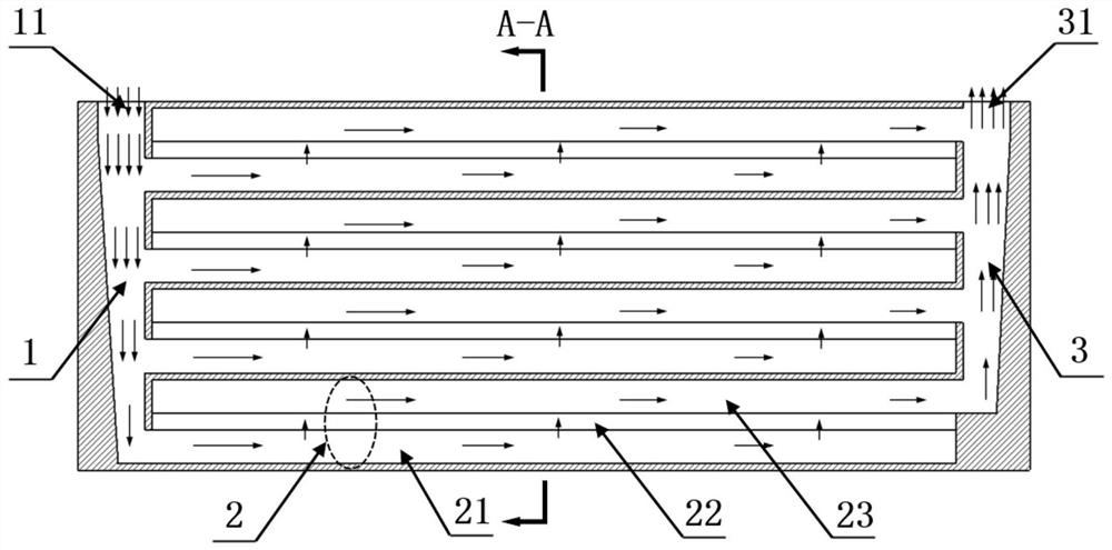
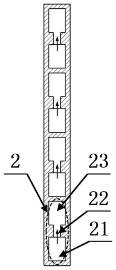
[0032] A tiny multi-channel boiling heat-exchange type uniform temperature cooling plate, comprising a cooling liquid inlet channel 1 on the left, four cooling liquid boiling combination multi-channels 2 evenly distributed along the vertical direction at the middle position, and a boiling gas outlet on the right Channel 3; the liquid cooling medium is input from the cooling liquid inlet channel 1 to the four cooling liquid boiling combination multi-channels 2, exchanges heat with the cooled object on the side wall of the cooling plate, boils and vaporizes, and finally exits from the boiling gas outlet Channel 3 discharges.

[0033] like figure 1 As shown, the cooling liquid inlet channel 1 and the boiling gas outlet channel 3 are symmetrically arranged with respect to the cooling liquid boiling combined multi-channel 2;

[0034] The cooling liquid inlet channel 1 adopts a trapezoidal manifold structure that tapers along the flow direction of the liquid cooling working medium...
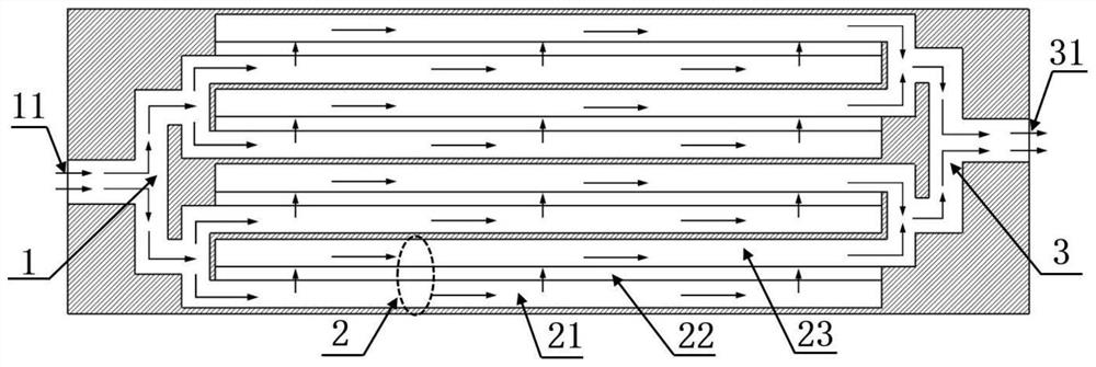
Embodiment 2

[0046] like image 3 As shown in the figure, this embodiment is basically the same as the embodiment 1, the only difference is that: the cooling liquid inlet channel 1 and the boiling gas outlet channel 3 both adopt a branched manifold structure, and the distribution direction of each pipe of the branched manifold structure is the same as that of the cooling liquid. The lateral directions of the boiling combined multi-channels 2 are parallel, and the total liquid inlet 11 of the cooling liquid inlet channel 1 and the gas total outlet 31 of the boiling gas outlet channel 3 are both located at the header end of the branched manifold structure.

Embodiment 1

[0047] Compared with Embodiment 1, this embodiment is more suitable for the even distribution of the liquid cooling medium under the conveying of the driving head, and the uniform distribution effect is better.

[0048] A verification calculation is performed for the above two embodiments, wherein the calculation adopts HFE-7000 working fluid, and its saturated boiling point under normal pressure is 307.15K. The obtained cloud image is in the shape of horizontal lines, which is completely different from the surface temperature cloud image of the traditional parallel flow micro multi-channel cooling plate. For details, see Figure 4 and Figure 5 ;

[0049] Figure 4 and Figure 5 The surface temperature nephogram of the conventional parallel flow micro-multi-channel cooling plate and the surface temperature nephogram of the uniform temperature cooling plate of the present invention (unit: K) are respectively represented. It can be clearly seen from the figures that the The...


PUM


Abstract

The invention relates to a micro multi-channel boiling heat exchange type uniform-temperature cooling plate which comprises a cooling liquid inlet channel on the left side, at least two cooling liquid boiling combined multi-channels evenly distributed in the middle in the vertical direction and a boiling gas outlet channel on the right side. And each cooling liquid boiling combined multi-channel is composed of a liquid cross-flow straight channel, a gas rising narrow channel and a gas cross-flow straight channel which are sequentially communicated from bottom to top, so that a liquid cooling working medium input from the cooling liquid inlet channel is boiled and gasified when exchanging heat with a cooled object, flows upwards and is discharged from the boiling gas outlet channel. According to the invention, high-heat-flux heat transfer of boiling heat transfer of the micro-channel can be realized, high uniformity of the temperature of the cooling plate can be ensured, and the cooling plate is suitable for heat dissipation and cooling of high-power power electronic components or new energy automobile power batteries.

Description

technical field [0001] The invention belongs to the technical field of high heat flux density cooling, and in particular relates to a tiny multi-channel boiling heat-exchange type uniform temperature cooling plate. Background technique [0002] In recent years, with the continuous development of micro-nano processing technology, the development of micro-electromechanical systems, large-scale integrated circuits and high-power lasers has also made great progress. Advanced technology industries such as aerospace, nuclear energy technology, energy power, and electric vehicles are paying more and more attention to the miniaturization and integration of electronic equipment. The trend of power improvement and miniaturization of electronic equipment has led to a continuous increase in the heat flux of its heat generation. For example, the average heat flux density of computer chips can reach 100W / cm 2 , in which the heat flux density of the local hot spot reaches 500W / cm 2 ; For...

Claims


Application Information

Patent Timeline
Patent Type & Authority Applications(China)
IPC IPC(8): F28D15/02
CPCF28D15/02Y02D10/00
Inventor 唐志国印超邓峰程建萍
Owner HEFEI UNIV OF TECH
Why Eureka
Try Eureka