Horizontal omnidirectional earthquake isolation system for building and building system

A seismic isolation system and horizontal technology, applied in the direction of buildings, building types, building components, etc., can solve the problems of bonding failure between rubber sheets and steel plates, compression shear failure, failure of seismic isolation bearings, etc., and achieve design mechanics calculation simplification, The effect of reducing rolling friction resistance and strong vertical bearing capacity

Pending Publication Date: 2022-06-03
俞铄南
View PDF7 Cites 0 Cited by
  • Summary
  • Abstract
  • Description
  • Claims
  • Application Information

AI Technical Summary

Problems solved by technology

That is to say, in the face of small and medium-intensity earthquakes, the laminated steel plate rubber seismic isolation bearing has a certain effect on isolating horizontal ground motions, but in the face of medium and high intensity earthquakes (such as above 6 on the Richter scale), the laminated steel plate rubber seismic isolation bearing The protective effect of the support on the building is seriously insufficient
[0011] (3) The laminated steel plate rubber seismic isolation bearing has a serious defect of insufficient tensile strength
Since the rubber sheet in the isolation bearing is also a load-bearing part, the probability of inconsistent collapse of a large number of isolation bearings under pressure is greatly increased, which will easily lead to the failure of the overall isolation
Therefore, the current laminated steel plate rubber seismic isolation bearings can no longer meet the seismic isolation requirements of high-elevation, large-scale, and heavy-weight buildings.
[0013] (5) The bonding process between the rubber layer and the steel plate of the laminated steel plate rubber isolation bearing has the problem of compression and shear damage, and the bond between the rubber sheet and the steel plate fails, resulting in failure or disintegration of the isolation bearing
However, in the past 30 years, architectural designs around the world have become more diverse, resulting in more complex mechanical calculations for seismic isolation design using laminated steel plate rubber isolation bearings. The main reason is that for larger buildings, multiple Laminated steel plate rubber seismic isolation bearing, and the weight distribution of each part of the building is different, the load-bearing capacity and other requirements for each laminated steel plate rubber seismic isolation bearing are not the same, for each laminated steel plate rubber isolation bearing Seismic bearings need to recalculate how many layers of steel plates and how many layers of rubber need to be used according to their respective load-bearing capacity and other requirements. However, the mechanical model of the horizontal plastic deformation of rubber is very complicated, and the design and calculation are very complicated; this makes the construction more difficult. Significant increase in design and construction costs for laminated steel plate rubber isolation
[0015] (7) Since the rubber sheet in the laminated steel plate rubber shock-isolation bearing needs to be glued to the steel plate, the cost of the sticking process is very expensive, making the laminated steel plate rubber shock-isolation bearing generally expensive, which cannot meet the comparison of construction costs The cost budget requirements of sensitive civil buildings and rural buildings are also one of the important reasons why more than 80% of the civil buildings in the world's active seismic zone do not use laminated steel plate rubber isolation technology to protect buildings and personal property
However, the laminated steel plate rubber isolation bearing needs a sufficient number of rubber sheets to form horizontal plasticity, so the height cannot be made small. The height of the current mainstream laminated steel plate rubber isolation bearing is about 40cm

Method used


Image

  • Horizontal omnidirectional earthquake isolation system for building and building system
  • Horizontal omnidirectional earthquake isolation system for building and building system
  • Horizontal omnidirectional earthquake isolation system for building and building system

Examples


Embodiment Construction

[0087] In order to have a clearer understanding of the technical features, purposes and effects of the present invention, specific embodiments of the present invention will now be described with reference to the accompanying drawings.

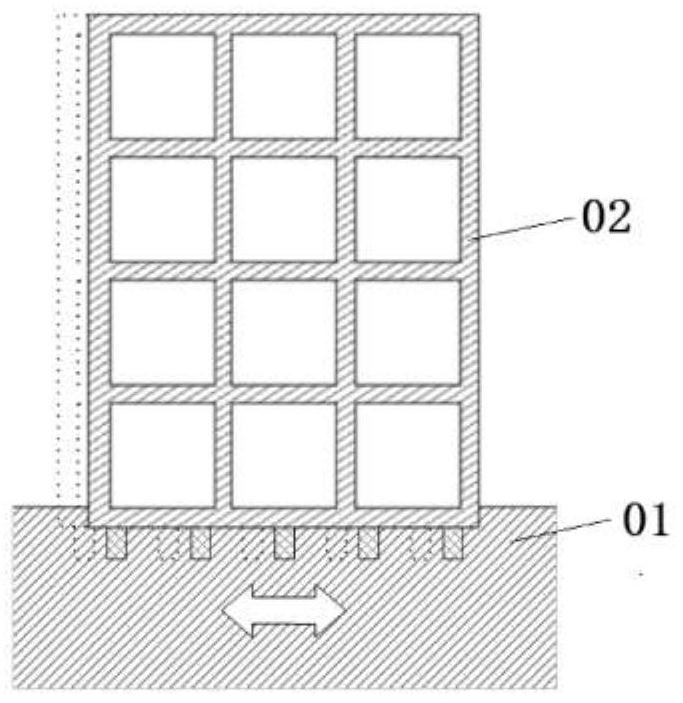
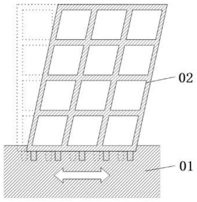
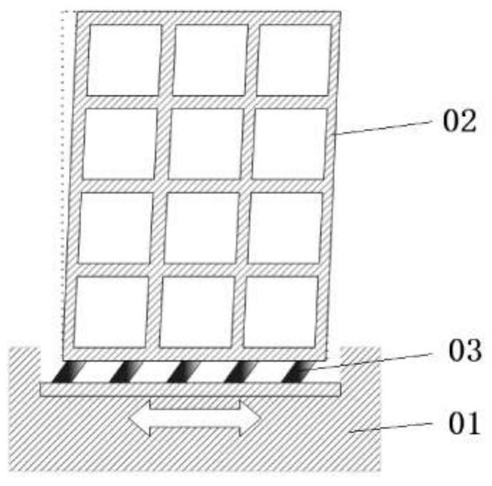
[0088] like Figure 1 to Figure 30 As shown, this embodiment provides a horizontal omnidirectional seismic isolation system for buildings, including an upper plate body 1 and a lower plate body 2 arranged in parallel and spaced apart, and spaced between the upper plate body 1 and the lower plate body 2 There is a first retainer 3 (that is, a gap is left between the first retainer 3 and the upper plate body 1 and the lower plate body 2 in the vertical direction), and a plurality of first retainers are arranged in the first retainer 3 The steel balls 31 and the first steel balls 31 are in rolling contact with the lower surface of the upper plate body 1 and the upper surface of the lower plate body 2 . An upper partition wall 11 is protruded down...


PUM


Abstract

The invention relates to a horizontal omnidirectional earthquake isolation system for a building and a building system, the earthquake isolation system comprises an upper plate body and a lower plate body, first retainers are arranged between the upper plate body and the lower plate body at intervals, a plurality of first steel balls are arranged in the first retainers, and the first steel balls are in rolling contact with the upper plate body and the lower plate body. An upper partition wall is arranged on the lower surface of the upper plate body in a downwards-protruding mode, and a lower partition wall is arranged on the upper surface of the lower plate body in an upwards-protruding mode. The upper partition wall, the lower partition wall and the first retainer are arranged at intervals in the horizontal direction, a rubber ring is clamped and fixed between every two adjacent partition walls, and a plurality of mutually independent bubble chambers are uniformly formed in each rubber ring at intervals in the circumferential direction. According to the invention, the vertical bearing capacity is relatively large, the overall height is relatively small, the horizontal rigidity is very low, the self-homing capacity is realized, the excellent horizontal seismic isolation capacity is realized, the seismic oscillation possibly from any horizontal direction can be dealt with, the building above can be effectively protected, and the design cost, the construction cost and the manufacturing cost are relatively low.

Description

technical field [0001] The invention relates to the technical field of anti-seismic buildings, in particular to a horizontal omnidirectional seismic isolation system and a building system for buildings. Background technique [0002] In the code for seismic design of modern buildings, the objectives of seismic fortification are "not damaged in small earthquakes", "repairable in moderate earthquakes", and "not collapsed in large earthquakes". Its design idea is based on "resistance", relying on the strength and plastic deformation capacity of the structural frame of the building itself to resist earthquake action and absorb seismic energy. like figure 1 and figure 2 As shown in the figure, since the foundation 01 of the earthquake-resistant building is consolidated on the ground, the seismic action of the building 02 is gradually amplified from the bottom to the top during an earthquake, thereby causing damage to the structural components, and people in the building will al...

Claims


Application Information

Patent Timeline
Patent Type & Authority Applications(China)
IPC IPC(8): E04B1/98E04H9/02E04B2/74E04B1/00
CPCE04B1/98E04H9/02E04B2/74E04B1/00
Inventor 俞铄南
Owner 俞铄南
Why Eureka
Try Eureka