
Method for decarburizing from concentrated carbon dioxide emission source based on wet-process regenerated carbon dioxide capture material

A carbon dioxide and capture material technology, applied in chemical instruments and methods, separation methods, filter regeneration, etc., can solve the problems of high cost, high investment and operation costs, and achieve high cost, high regeneration energy consumption, and simple processing technology Effect

Pending Publication Date: 2022-05-31
霖和气候科技(北京)有限公司
View PDF7 Cites 2 Cited by
  • Summary
  • Abstract
  • Description
  • Claims
  • Application Information

AI Technical Summary

Problems solved by technology

However, its repeated compression and condensation will bring huge energy loss and additional carbon emissions, and its equipment investment and operation costs are high, which further increases the cost

Method used


Image

  • Method for decarburizing from concentrated carbon dioxide emission source based on wet-process regenerated carbon dioxide capture material
  • Method for decarburizing from concentrated carbon dioxide emission source based on wet-process regenerated carbon dioxide capture material
  • Method for decarburizing from concentrated carbon dioxide emission source based on wet-process regenerated carbon dioxide capture material

Examples


Embodiment

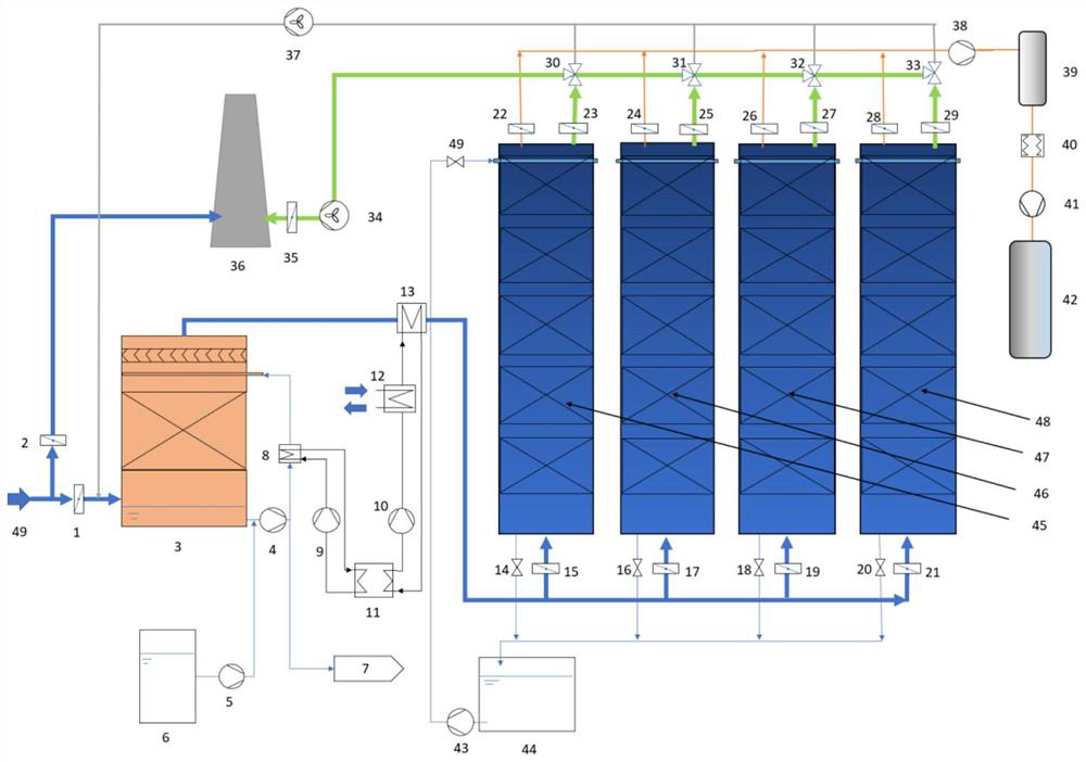
[0057] see image 3 , image 3 The process flow chart of the method for decarbonizing from concentrated carbon dioxide emission sources based on wet regeneration of carbon dioxide capture materials provided by the embodiment of the present invention; wherein, 1, 2, 15, 17, 19, 21, 22, 23, 24 , 25, 26, 27, 28, 29, 35 - gas valve, 3 - direct contact condenser, 4, 5, 9, 10, 43 - pump, 14, 16, 18, 20, 49 - water valve, 30 , 31, 32, 33-gas three-way valve, 34, 37-fan, 38-vacuum pump, 41-compressor, 6-alkali tank, 7-waste water, 8, 12, 13-heat exchanger, 11 -Heat pump, 36-Exhaust tube, 39-Gas buffer tank, 40-Dehumidifier, 42-CO2 storage tank, 44-Circulating water tank, 45, 46, 47, 48-Carbon with wet regeneration CO2 capture material Capture unit, 49 - flue gas inlet.

[0058] The specific working process is as follows:

[0059] Flue gas from industrial processes (including but not limited to concentrated CO in power plants, steel mills, cement plants, chemical plants, etc. 2 em...


PUM


Abstract

A method for decarburizing from a centralized carbon dioxide emission source based on a wet-process regenerated carbon dioxide capture material comprises the following steps: condensing and heating flue gas from the centralized carbon dioxide emission source, and respectively introducing the flue gas into a plurality of groups of carbon capture units connected in parallel to dry the wet-process regenerated carbon dioxide capture material in the carbon capture units; carrying out CO2 adsorption by adopting the dried wet-process regenerated CO2 trapping material, and then carrying out CO2 desorption on the wet-process regenerated CO2 trapping material subjected to CO2 adsorption in a water spraying manner; pumping the obtained CO2 into a buffer device by adopting a vacuum pump, and then sequentially dehumidifying and compressing to obtain CO2 gas for storage; and repeating the steps to continuously produce gas or intermittently produce gas through a plurality of groups of carbon capture units which are connected in parallel and are filled with wet-process regenerated CO2 capture materials, so as to realize decarburization from a centralized carbon dioxide emission source. According to the method, specific steps, conditions and parameters are adopted, overall good interaction is achieved, the material, equipment and operation cost can be reduced, the product gas purity is improved, and the method has wide application prospects.

Description

technical field [0001] The present invention relates to CO 2 The field of capture and removal technology, more specifically, relates to a method for decarbonizing concentrated carbon dioxide emission sources based on wet-process regenerated carbon dioxide capture materials. Background technique [0002] Carbon dioxide is the main greenhouse gas, and the serious consequences of excessive carbon dioxide emissions have not been allowed to be ignored by any country. According to the latest assessment report released by the United Nations Intergovernmental Panel on Climate Change (IPCC), if the global temperature rises by 1.5°C, extreme weather including high temperature, storms, floods and their damage will increase, and global warming will affect biodiversity and ecology. The impact of the system has increased significantly, and climate-related risks to health, livelihoods, food security, water supply, human security and economic growth are projected to increase with global wa...

Claims


Application Information

Patent Timeline
Patent Type & Authority Applications(China)
IPC IPC(8): B01D53/02B01J20/34C01B32/50
CPCB01D53/02B01J20/3475C01B32/50B01D2257/504B01D2258/0283Y02P20/151
Inventor 王凯李锋朱亮亮陈曦
Owner 霖和气候科技(北京)有限公司
Learn More