Ceiling reflection resistant projection screen and projection system
A projection screen and ceiling technology, applied in optics, instruments, projection devices, etc., can solve problems such as poor definition of projection screens
- Summary
- Abstract
- Description
- Claims
- Application Information
AI Technical Summary
Problems solved by technology
Method used
Image
Examples
Embodiment 1
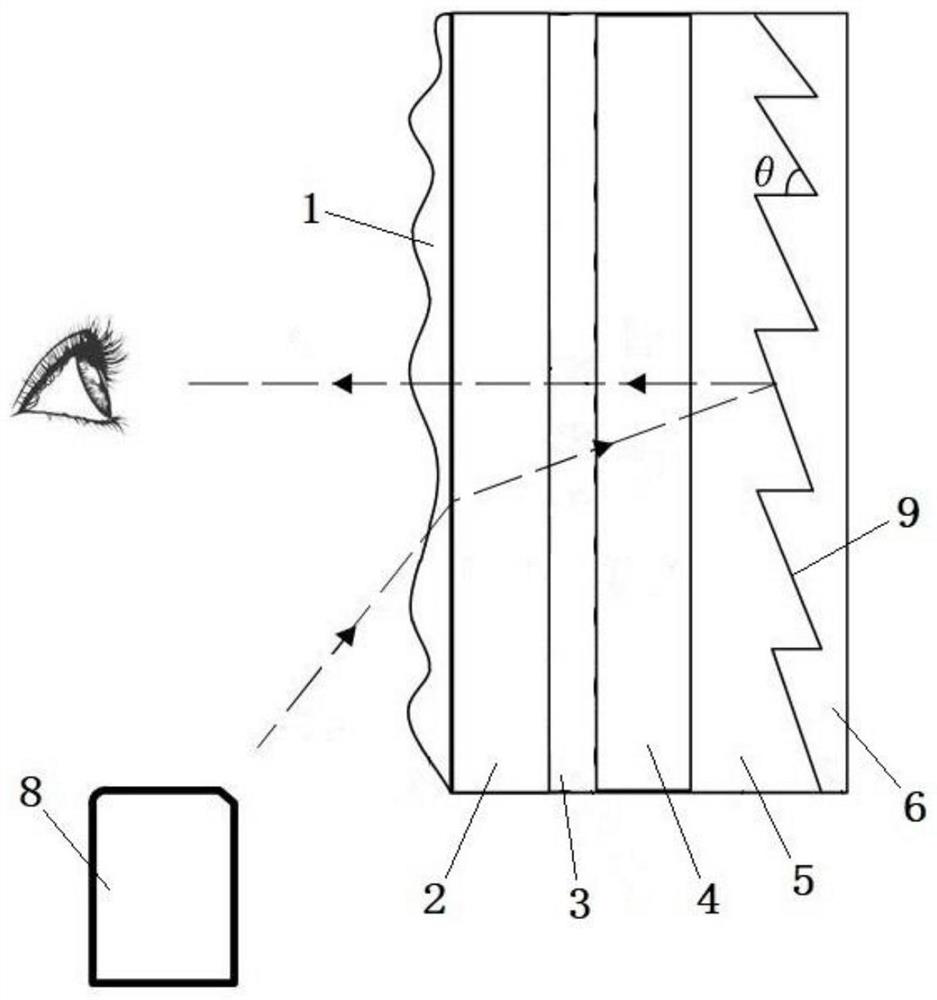
[0045] In the field of ultra-short-focus laser projection display, in order to achieve better brightness and display effect, a projection screen including a Fresnel lens layer is generally selected and used with a projector. This projection screen is characterized by high gain and small viewing angle. And has a certain anti-environmental light effect. The projection screen in the prior art generally includes a surface layer, a diffusion layer, a Fresnel lens layer and a reflective layer that are arranged in sequence. It cannot be curled, and has great limitations during transportation and use; in addition, the diffusion layer realizes the diffusion of light through the diffusion particles distributed in the MS material, and the degree of diffusion is higher, and the higher the degree of diffusion of light, the clarity of the projection screen. the worse.
[0046] In view of the above reasons, the present invention provides an anti-ceiling reflection projection screen to impro...
Embodiment 2
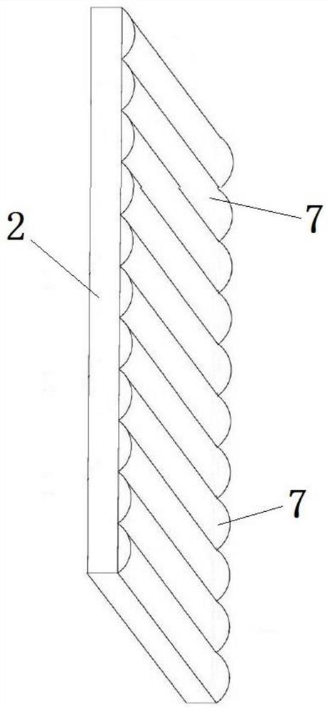
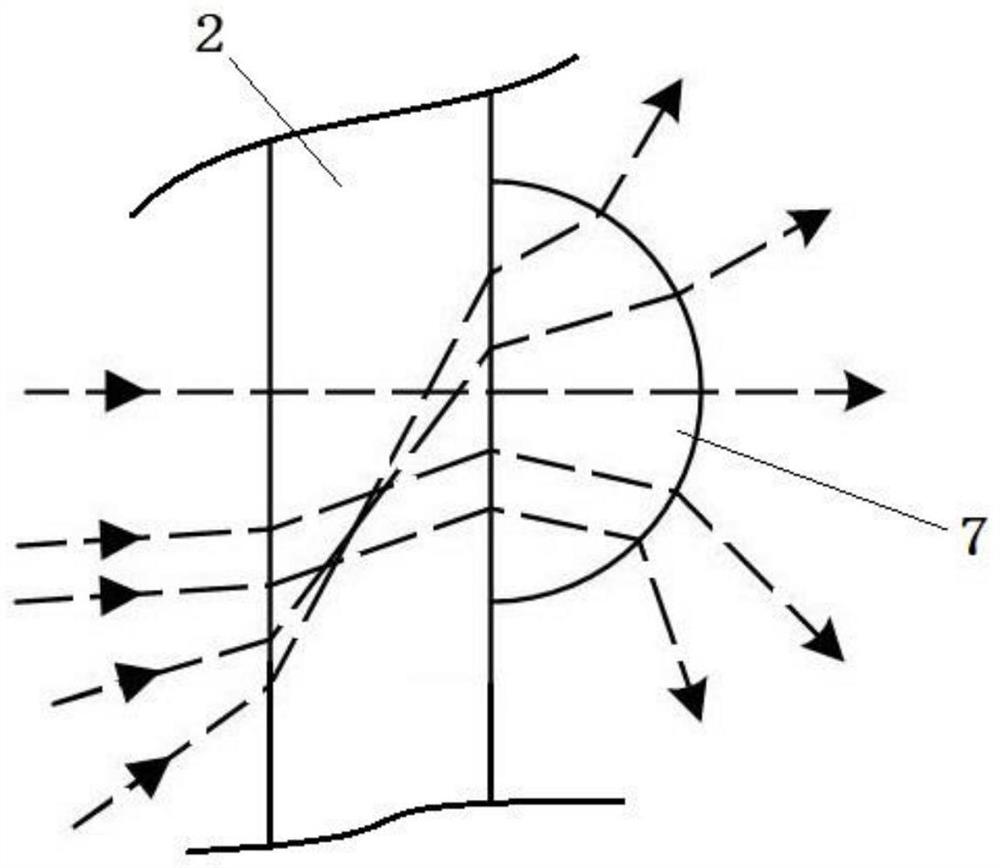
[0065] The difference from Example 1 is that: Figure 4 As shown, the light-scattering layer 3 includes a base layer 12, and the base layer 12 is made of UV glue. Because the UV glue has elasticity, the base layer 12 can be curled, so that the light-scattering layer 3 can be curled. The side of the base layer 12 away from the first support layer 2 is provided with a plurality of long grooves 13, the long grooves 13 are linear grooves, and the long grooves 13 are semicircular grooves, that is, the long grooves 13 are intercepted by a plane perpendicular to its extending direction. The shape of the simulated cross-section is a semicircle, and in the longitudinal extension direction of the long groove 13, the size of the simulated cross-section is the same everywhere, and the long groove 13 is cut by a plane perpendicular to its extension direction. Located on the side of the arc away from the first support layer 2, the contour of the semicircular simulated cross-section graduall...
Embodiment 3
[0072] The difference from Example 1 is that: Figure 5 As shown, the light-scattering layer 3 is provided with two layers, both of which are located between the first support layer 2 and the second support layer 4, wherein one layer of the light-scattering layer 3 is attached to the first support layer 2, and the other layer is The light-scattering layer 3 is attached to the second support layer 4 , and the two light-scattering layers 3 are bonded and fixed by OCA glue. After the two light-scattering layers 3 are glued and fixed, the elongated protrusions of the two light-scattering layers 3 together form a plurality of cavities for accommodating air.
[0073] It should be noted that the extending directions of the elongated protrusions of the two astigmatism layers 3 in the present embodiment 3 are perpendicular to each other, specifically: each elongated protrusion in the astigmatism layer 3 attached to the first support layer 2 along the Extending in the vertical directio...
PUM
| Property | Measurement | Unit |
|---|---|---|
| Diameter | aaaaa | aaaaa |
Abstract
Description
Claims
Application Information
 - Generate Ideas
- Intellectual Property
- Life Sciences
- Materials
- Tech Scout
- Unparalleled Data Quality
- Higher Quality Content
- 60% Fewer Hallucinations
Browse by: Latest US Patents, China's latest patents, Technical Efficacy Thesaurus, Application Domain, Technology Topic, Popular Technical Reports.
© 2025 PatSnap. All rights reserved.Legal|Privacy policy|Modern Slavery Act Transparency Statement|Sitemap|About US| Contact US: help@patsnap.com


