Automatic welding equipment for single crystal furnace

An automatic welding and single crystal furnace technology, applied in the direction of welding equipment, auxiliary welding equipment, welding/cutting auxiliary equipment, etc., can solve the problems of rising temperature of grinding rods, failure of waste gas treatment, damage to grinding rods, etc., to avoid the impact of burrs The effect of welding, reducing the frequency of replacement and prolonging the service life

Active Publication Date: 2022-05-17
CHANGZHOU LEMENG PRESSURE VESSEL CO LTD
View PDF13 Cites 0 Cited by
  • Summary
  • Abstract
  • Description
  • Claims
  • Application Information

AI Technical Summary

Problems solved by technology

[0003] During the production of the single crystal furnace, it is necessary to weld between the top of the furnace body and the top accessories. When welding, welding equipment is required. The existing welding equipment cannot handle a large amount of waste gas generated by welding. As a result, exhaust gas floats into the air and pollutes the air, which is not conducive to environmental protection. In addition, when the existing welding equipment is in use, in order to avoid the burrs on the welding surface from affecting the welding, the burrs are usually polished by the grinding rods installed on the welding equipment. When grinding, the position of the grinding rod is fixed, so that the contact surface with the burr is fixed, resulting in one area of ​​the grinding rod always in contact with the burr, resulting in excessive wear and tear, requiring frequent replacement of the grinding rod, and continuous use of the same grinding rod for work will be difficult As a result, the temperature of the grinding rod continues to rise and damage the grinding rod

Method used


Image

  • Automatic welding equipment for single crystal furnace
  • Automatic welding equipment for single crystal furnace
  • Automatic welding equipment for single crystal furnace

Examples


Embodiment Construction

[0030] In order to make the purpose, technical solutions and advantages of the embodiments of the present invention more clear, the technical solutions in the embodiments of the present invention will be clearly and completely described below in conjunction with the accompanying drawings in the embodiments of the present invention. Obviously, the described embodiments It is a part of embodiments of the present invention, but not all embodiments. Based on the embodiments of the present invention, all other embodiments obtained by persons of ordinary skill in the art without making creative efforts belong to the protection scope of the present invention.

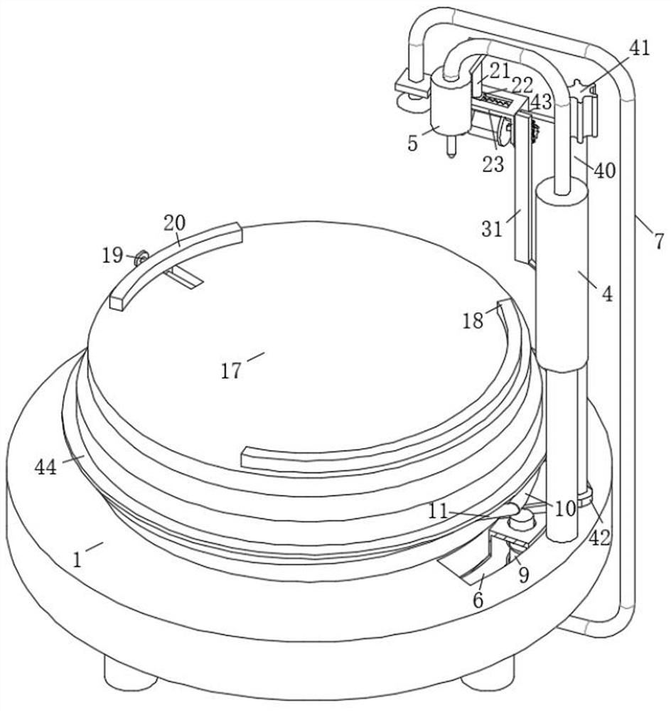
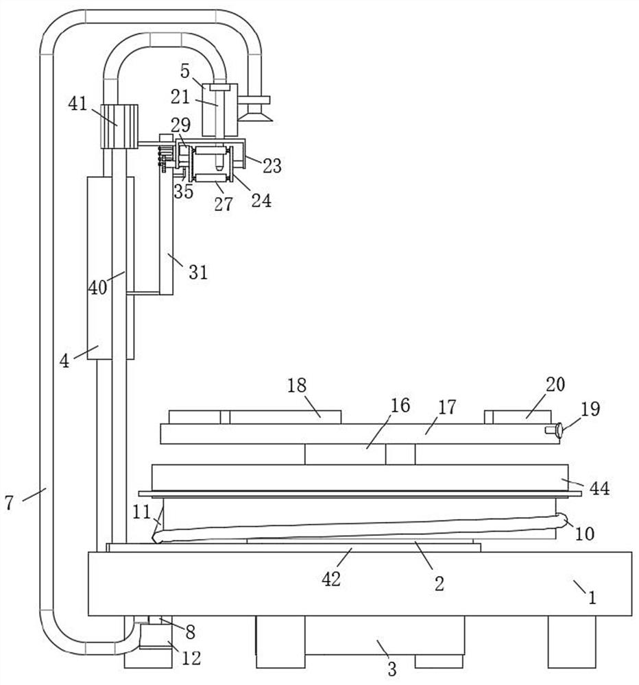
[0031] The invention provides an automatic welding equipment for a single crystal furnace, such as Figure 1-8 As shown, the device includes a base plate 1, a support column 2 is installed in the middle of the top end of the base plate 1 for rotation, a first motor 3 is fixedly installed at the bottom end of the base plate 1, ...


PUM


Abstract

The invention discloses automatic welding equipment for a single crystal furnace, and relates to the technical field of welding equipment. The equipment comprises a bottom plate, a supporting column is rotationally installed in the middle of the top end of the bottom plate, and a first motor is fixedly installed at the bottom end of the bottom plate. Waste gas generated in the welding process can be collected, purified and then exhausted, waste gas diffusion and air pollution can be avoided, the welding process is more environmentally friendly, burrs on the top wall of a furnace body can be polished while welding is conducted, the burrs are prevented from influencing welding, meanwhile, a polishing rod can move back and forth, and the welding efficiency is improved. One part of the grinding rod can be prevented from being in contact with the top wall of the furnace body for grinding all the time, so that the service life of the grinding rod can be prolonged, the replacement frequency of the grinding rod is reduced, the grinding rod can be switched after welding is finished, and the situation that the grinding rod is damaged due to continuous temperature rise caused by the fact that the same grinding rod is used all the time is avoided.

Description

technical field [0001] The invention belongs to the technical field of welding equipment, in particular to an automatic welding equipment for a single crystal furnace. Background technique [0002] The single crystal furnace is a kind of equipment that melts polycrystalline materials such as polycrystalline silicon with a graphite heater in an inert gas (mainly nitrogen and helium) environment, and grows a single crystal without dislocation by the Czochralski method. [0003] During the production of the single crystal furnace, it is necessary to weld between the top of the furnace body and the top accessories. When welding, welding equipment is required. The existing welding equipment cannot handle a large amount of waste gas generated by welding. As a result, exhaust gas floats into the air and pollutes the air, which is not conducive to environmental protection. In addition, when the existing welding equipment is in use, in order to avoid the burrs on the welding surface ...

Claims


Application Information

Patent Timeline
Patent Type & Authority Applications(China)
IPC IPC(8): B23K37/00B23K37/053B23P23/00
CPCB23K37/00B23K37/053B23P23/00
Inventor 潘燕萍朱海军
Owner CHANGZHOU LEMENG PRESSURE VESSEL CO LTD
Why Eureka
Try Eureka