
Direct-current bus voltage clamping circuit of servo driver

A DC bus voltage, servo driver technology, applied in the direction of emergency protection circuit devices, circuit devices, emergency protection circuit devices for limiting overcurrent/overvoltage, etc. voltage range, driver damage, etc.

Pending Publication Date: 2022-05-13
PHASE MOTION CONTROL SOLUTION WUHAN CO LTD
View PDF0 Cites 0 Cited by
  • Summary
  • Abstract
  • Description
  • Claims
  • Application Information

AI Technical Summary

Problems solved by technology

With the wide application of servo drives in machine tools, rubber and plastics, transportation, electric power and other equipment, due to the existence of some force majeure factors, the damage of the drive due to overvoltage occurs from time to time, and the current commonly used braking module scheme has the following shortcomings: First, when the signal circuit of the control module loses power, the DC bus voltage cannot be effectively controlled within a safe voltage range, resulting in damage to the drive; The motor is still running at high speed, and the DC bus voltage caused by the back electromotive force of the motor continues to rise uncontrollably, causing damage to the driver; third, some drivers have a sequence requirement for power supply, that is, the control power is given first and then the AC power, but due to misoperation Reverse the power supply sequence and when the AC voltage is also abnormally high, the brake module circuit cannot effectively control the brake module to maintain the bus voltage in a safe voltage range, resulting in damage to the drive

Method used


Image

  • Direct-current bus voltage clamping circuit of servo driver
  • Direct-current bus voltage clamping circuit of servo driver

Examples


Embodiment Construction

[0019] The principles and features of the present invention are described below in conjunction with the accompanying drawings, and the examples given are only used to explain the present invention, and are not intended to limit the scope of the present invention.

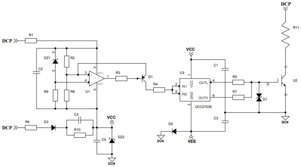
[0020] like figure 1 As shown, a DC bus voltage clamping circuit of a servo drive includes a resistor step-down circuit, a capacitor voltage divider circuit, a comparison circuit, a signal conditioning circuit, a drive circuit and a switch circuit, and the positive pole of the DC bus is connected to the resistor step-down circuit respectively. The input terminal is electrically connected to the input terminal of the capacitor voltage divider circuit, and the output terminal of the resistance step-down circuit and the output terminal of the capacitor voltage divider circuit are respectively electrically connected to the positive input terminal and the negative input terminal of the comparison circuit, and the The out...


PUM


Abstract

The invention relates to a direct current bus voltage clamping circuit of a servo driver, which comprises a resistance step-down circuit, a capacitance voltage division circuit, a comparison circuit, a signal conditioning circuit, a driving circuit and a switching circuit, and is characterized in that the positive electrode of a direct current bus is electrically connected with the resistance step-down circuit and the capacitance voltage division circuit respectively; the resistance step-down circuit and the capacitance voltage division circuit are electrically connected with the comparison circuit, the comparison circuit is electrically connected with the signal conditioning circuit, the signal conditioning circuit, the driving circuit and the switching circuit are sequentially connected in series, and the switching circuit is electrically connected between the positive electrode and the negative electrode of a direct-current bus. The resistance step-down circuit and the capacitance voltage division circuit are used for carrying out step-down and voltage division processing on the direct-current bus voltage respectively, and when the direct-current bus voltage exceeds a certain value, the negative input voltage of the comparison circuit is higher than the positive input voltage, so that a signal at the output end of the comparison circuit is turned over, and the switching circuit is controlled to be switched on; therefore, the DC bus voltage is clamped in a safe range, and the safety of the servo driver is ensured.

Description

technical field [0001] The invention relates to the technical field of electronic circuits, in particular to a DC bus voltage clamping circuit of a servo drive. Background technique [0002] In the prior art, the servo driver is composed of a rectification module, a filter module, a control module, an inverter module and a brake module. It converts the alternating current into direct current through the rectification module, charges the capacitor of the filter module, and the signal of the control module enters the inverter module and the braking module through isolation and drive, and the inverter module inverts the direct current into frequency-adjustable alternating current. Control the operation of the motor, and the brake module is to maintain the DC bus voltage of the driver within a certain voltage range to ensure that the driver is not damaged by excessive voltage. With the wide application of servo drives in machine tools, rubber and plastics, transportation, elect...

Claims


Application Information

Patent Timeline
Patent Type & Authority Applications(China)
IPC IPC(8): H02H9/04H02P29/024H02P27/06
CPCH02H9/04H02P29/0241H02P27/06
Inventor 康鹏任文杰杨合跃仇一鸣秦兴权徐陈夏夏风陈泽凯
Owner PHASE MOTION CONTROL SOLUTION WUHAN CO LTD
Learn More