Built-in vortex combustion device and combustion system for disposing RDF through cement decomposing furnace

A kind of combustion device, built-in technology, applied in the direction of burning fuel in molten state, fluidized bed combustion equipment, combustion type, etc., can solve the problems of large fluctuations in calorific value and ash content, high cost, slow combustion speed, etc., to achieve effective Conducive to the operation of the system, improve the scope of application, and improve the effect of disposal volume

Pending Publication Date: 2022-05-13
SINOMA INT ENG
View PDF0 Cites 0 Cited by
  • Summary
  • Abstract
  • Description
  • Claims
  • Application Information

AI Technical Summary

Problems solved by technology

Based on cost considerations, RDF is generally pretreated by sorting and crushing municipal solid waste. Its moisture content is high, its calorific value and ash content fluctuate greatly, and the quality of RDF is low. It is used as a substitute for cement calciner. Fuel, which has a great impact on the stable operation of the firing system and clinker production and quality, resulting in a generally low fuel substitution rate
[0003] The existing devices used for cement decomposition furnace to replace fuel RDF combustion mainly include F.L.Smidth's HOTDISC hot plate furnace, ThyssenKrupp's PREPOL-SC ladder furnace, KHD's etc. Compared with the cement calciner, they are all external, and the following problems generally exist in the use of external pre-combustion devices: (1) RDF is mainly piled up in the pre-combustion device, and the combustion speed is slow, which affects the RDF disposal capacity ; (2) A tertiary air needs to be introduced separately, which will affect the wind control and operation stability of the cement clinker burning system; (3) The ash generated after combustion enters into decomposition in a discontinuous or stranding manner furnace, it is easy to cause fluctuations in the operating conditions of the system; (4) The structure of the device is complex, the weight and space occupied are large, the system is complicated, and the cost is high

Method used


Image

  • Built-in vortex combustion device and combustion system for disposing RDF through cement decomposing furnace
  • Built-in vortex combustion device and combustion system for disposing RDF through cement decomposing furnace
  • Built-in vortex combustion device and combustion system for disposing RDF through cement decomposing furnace

Examples


Embodiment Construction

[0017] The technical solutions of the present invention will be described in detail below in combination with specific implementation methods and accompanying drawings.

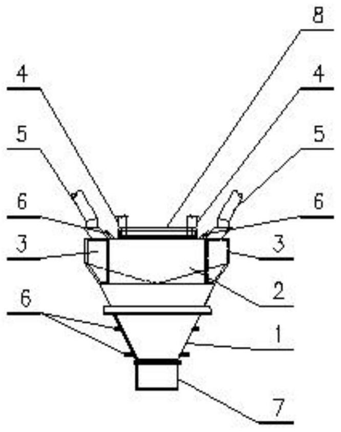
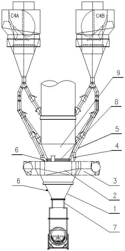
[0018] The calciner substitute fuel RDF completes drying, gasification and primary combustion in the built-in vortex combustion device of the present invention, and partially or completely replaces the fuel coal of the cement calciner. Such as figure 1 As shown, the built-in vortex combustion device of the present invention includes a first cylinder 1 and a second cylinder 2 , and the second cylinder 2 is connected above the first cylinder 1 and communicated with the first cylinder 1 . The outer shells of the first cylinder 1 and the second cylinder 2 are made of steel plates, and the inner linings are made of fire-resistant and heat-insulating materials, so as to improve the overall firmness and high-temperature resistance of the device. The second barrel 2 adopts a cylindrical structure with a volute, and ...


PUM


Abstract

The invention discloses a built-in vortex combustion device and a combustion system for disposing RDF through a cement decomposing furnace. The built-in vortex combustion device comprises a first barrel and a second barrel, and the second barrel is connected to the upper portion of the first barrel and communicates with the first barrel; the second barrel is of a cylindrical structure with a volute, and a plurality of tertiary air inlets are evenly distributed in the rotary cutting line of the volute. A plurality of RDF feeding ports are formed in the top surface of the second barrel; and a preheated raw material feeding opening is formed in the top surface of the second barrel body and is positioned on the outer side of the tertiary air inlet. The RDF can be in a suspended state in the vortex combustion device, the combustion speed is far higher than stacking combustion, the vortex combustion device is arranged to be of a built-in structure, and tertiary air does not need to be introduced independently.

Description

technical field [0001] The invention relates to the field of cement production and the application of alternative fuels, in particular to a built-in vortex combustion device and a combustion system for treating RDF in a cement decomposition furnace. Background technique [0002] At present, the use of refuse-derived fuel (RDF) as an alternative fuel for cement calciners is becoming more and more widely used, and more and more cement plants are beginning to use RDF as fuel for cement calciners, partially or completely replacing traditional fossil fuel coal. Based on cost considerations, RDF is generally pretreated by sorting and crushing municipal solid waste. Its moisture content is high, its calorific value and ash content fluctuate greatly, and the quality of RDF is low. It is used as a substitute for cement calciner. Fuel has a great impact on the stable operation of the firing system and the production and quality of clinker, resulting in a generally low fuel substitutio...

Claims


Application Information

Patent Timeline
Patent Type & Authority Applications(China)
IPC IPC(8): F23C10/00F23C10/18F23C10/20F23C10/22
CPCF23C10/00F23C10/18F23C10/20F23C10/22
Inventor 刘仁越黄巧丽陈翼宁建根黄锋周斌宿向超孙德群潘轶朱刚赵美江
Owner SINOMA INT ENG
Why Eureka
Try Eureka