Horizontal electrolytic electric spark machining device and method

A machining device and electric spark technology, applied in the field of horizontal electrolytic EDM devices, can solve the problems of slow efficiency and limited machining range, and achieve the effects of expanding the machining range, stabilizing the state of electric discharge machining, and improving machining efficiency

Active Publication Date: 2022-05-13
JIANGSU UNIV OF TECH
View PDF20 Cites 0 Cited by
  • Summary
  • Abstract
  • Description
  • Claims
  • Application Information

AI Technical Summary

Problems solved by technology

However, this technology mainly solves the problem of micro-EDM of holes or micro-groove parts, and realizes more efficient "point" processing. When it is used in groove processing or seam processing, the processing range is limited. There is an obvious problem of slow efficiency

Method used


Image

  • Horizontal electrolytic electric spark machining device and method
  • Horizontal electrolytic electric spark machining device and method
  • Horizontal electrolytic electric spark machining device and method

Examples


Embodiment 1

[0031] In order to expand the processing range, solve the problem of high-efficiency processing of "line" and "surface" in the EDM process, and realize the processing of thicker non-conductive materials, a horizontal EDM device is disclosed in this embodiment.

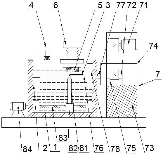
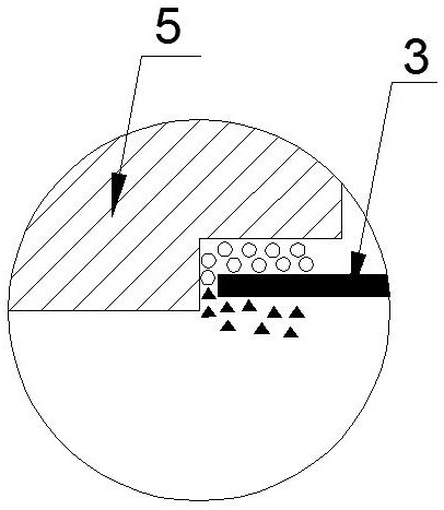
[0032] The device includes an electrolysis box 1, an auxiliary electrode 2, a tool electrode 3, a power supply 4, a workpiece 5, a feed adjustment system 6, and an electrode horizontal rotation system 7; connected, the tool electrode 3 is connected to the negative pole of the power supply 4, the tool electrode 3 and the workpiece 5 are immersed in the electrolyte at the same time, the tool electrode 3 is horizontally placed under the workpiece 5, and the workpiece 5 is connected to the feed adjustment system through the workpiece chuck The feed is controlled by the feed adjustment system, and the feed movement in the machining process is realized through the feed of the workpiece. The tool electrode 3 is connected with ...

Embodiment 2

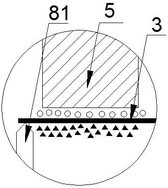
[0043] The only difference between this embodiment and the first embodiment is that a set of electrode supporting device 8 is arranged at the bottom of the electrolytic box, and the other structures are the same as those in the first embodiment.

[0044] When the length of the tool electrode 3 is short (<30 mm), the state of the electrode is relatively stable during the machining process, and there will be no obvious shaking at the end, but when the length of the tool electrode 3 is long (≥30 mm), the electrolytic machining process There will be a certain vibration in the process, which may have a certain impact on the stability of the processing process and the processing effect. In order to solve this problem, an electrode support device 8 is installed at the bottom of the electrolytic box 1, and the electrode support device 8 includes a support rod 81 , the movable block 82 and the screw mandrel 83, the screw mandrel 83 is placed horizontally at the bottom of the electrolyti...


PUM


Abstract

During machining, a tool electrode and a workpiece are immersed in electrolyte at the same time, the tool electrode is horizontally arranged below the workpiece, feeding of the workpiece is controlled by a feeding adjusting system, and rotation of the tool electrode is controlled by an electrode horizontal rotating system. According to the device, the relative position between the tool electrode and the workpiece in the traditional machining process is changed, and the workpiece is machined through the feeding movement of the workpiece. The layout form that a workpiece is inverted and a tool electrode is horizontally placed is adopted, linear or plane type machining is formed, the defect of single longitudinal point type machining of a conventional electrolysis electric spark machining device is overcome, the machining quality of a groove is greatly improved, corrosion removal products can be rapidly discharged out of electrodes under the action of gravity, the electrolyte flowing capacity in the machining process is enhanced, and the machining efficiency is improved. A stable gas film can be formed, so that the processing efficiency is improved.

Description

technical field [0001] The invention belongs to the technical field of special processing, and in particular relates to a horizontal electrolysis electric discharge processing device and method. Background technique [0002] In recent years, with the rapid development of modern industry and the continuous discovery of new difficult-to-machine materials, miniaturization and precision have become an important direction for the development of advanced manufacturing industries, and the processing requirements for complex and tiny parts are also getting higher and higher. At the same time, with the vigorous development of microelectromechanical systems, microfluidic systems, aerospace and other fields, heat-resistant glass, ceramics and other non-conductive hard and brittle materials with high temperature resistance, corrosion resistance, and high strength are more and more widely used. However, most of the hard and brittle materials are difficult to process, and the processing a...

Claims


Application Information

Patent Timeline
Patent Type & Authority Applications(China)
IPC IPC(8): B23H5/02
CPCB23H5/02Y02P70/10
Inventor 孔令蕾陈宁雷卫宁单星海段韶岚李志贤蹇文轩
Owner JIANGSU UNIV OF TECH
Why Eureka
Try Eureka