Power supply device, electric vehicle using same, and power storage device

A power supply device and battery technology, which is applied to the arrangement of multiple different prime movers of general power plants, the arrangement of cooling combination of power plants, electric vehicles, etc., to reduce frictional resistance and improve work efficiency.

Pending Publication Date: 2022-05-10
SANYO ELECTRIC CO LTD
View PDF2 Cites 0 Cited by
  • Summary
  • Abstract
  • Description
  • Claims
  • Application Information

AI Technical Summary

Problems solved by technology

In addition, it is known that the outer casing of the battery cell expands due to charging and discharging.

Method used


Image

  • Power supply device, electric vehicle using same, and power storage device
  • Power supply device, electric vehicle using same, and power storage device
  • Power supply device, electric vehicle using same, and power storage device

Examples


Embodiment approach 1

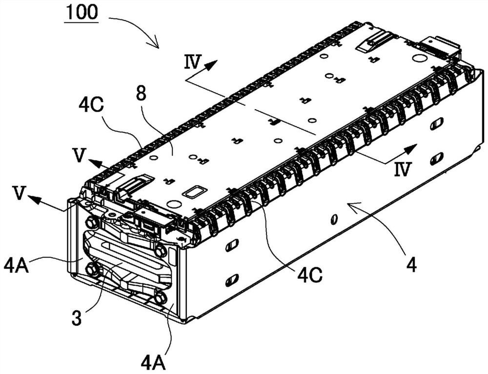
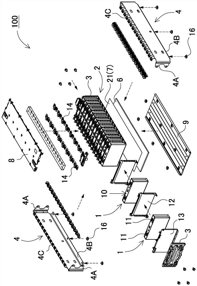
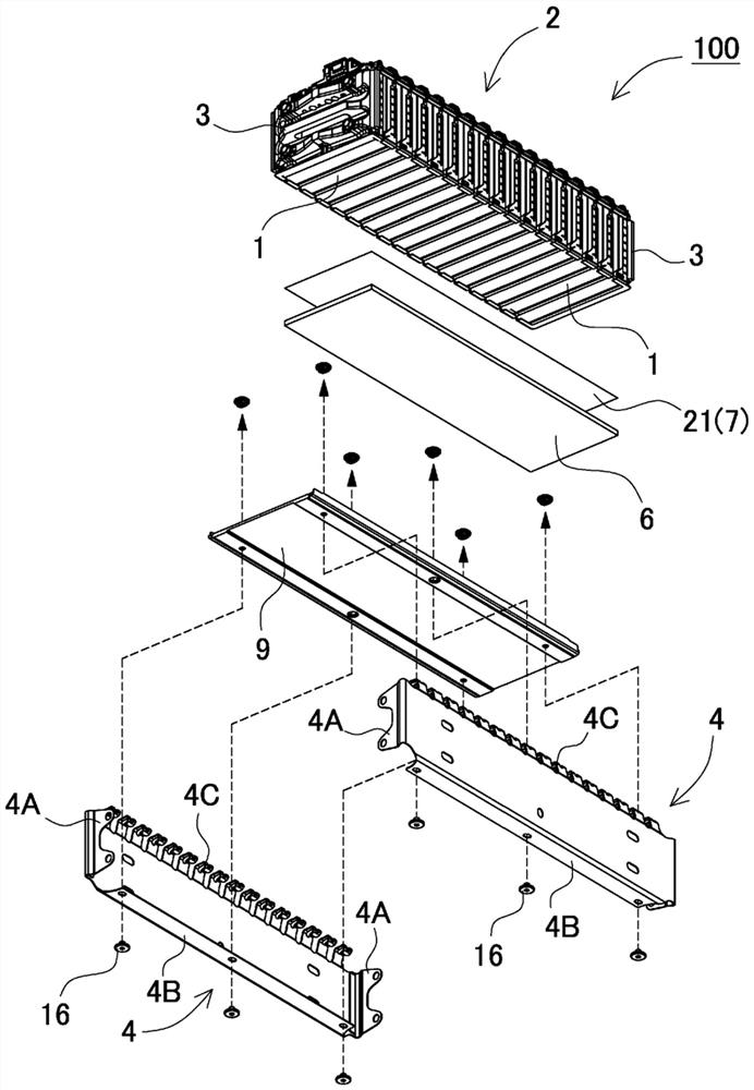
[0046] Figure 1 to Figure 5 Each shows a power supply device according to Embodiment 1 of the present invention. In these figures, figure 1 shows a perspective view of the power supply unit, figure 2 shows the view from obliquely above figure 1 The exploded perspective view of the power supply unit observed, image 3 shows the view from obliquely below figure 1 The exploded perspective view of the power supply unit observed, Figure 4 show figure 1 A vertical sectional view of the power supply unit along line IV-IV, Figure 5 show figure 1 The vertical section of the power supply device along the V-V line.

[0047] Such as Figure 1 to Figure 5 As shown, the power supply device 100 has: a plurality of battery cells 1, the external cans of which are set in a square shape; a pair of end plates 3, which cover both end faces of a battery stack 2 formed by stacking a plurality of battery cells 1; A plurality of tightening strips 4, which are plate-shaped extending ...


PUM

PropertyMeasurementUnit
thicknessaaaaaaaaaa

Abstract

In order to enable smooth sliding by reducing frictional resistance between the upper surface of a heat transfer sheet and the bottom surface of a battery cell while maintaining a heat transfer state between the battery cell and the heat transfer sheet, a power supply device is provided with: a plurality of battery cells (1) each having a square exterior can; a pair of end plates (3) that cover both end surfaces of a battery stack in which the plurality of battery cells (1) are stacked; a plurality of lacing strips which are plate-shaped and extend in the stacking direction of the plurality of battery cells (1), are respectively arranged on the opposite side surfaces of the battery stack, and fasten the end plates (3) to each other; a heat dissipation plate (9) on which the battery stack is placed on the upper surface side and which dissipates heat from the battery stack; and a heat transfer sheet (6) that is interposed between the upper surface of the heat dissipation plate (9) and the lower surface of the battery stack and that causes the heat dissipation plate (9) and the battery stack to be in a thermally coupled state, in which a low-friction sliding layer (7) having a lower frictional resistance than the frictional resistance of the upper surface of the heat transfer sheet (6) is provided between the heat transfer sheet (6) and the battery cells (1).

Description

technical field [0001] The present invention relates to a power supply device, an electric vehicle using the power supply device, and a power storage device. Background technique [0002] The power supply device is used in a power supply device for driving an electric vehicle, a power supply device for storing electricity, and the like. In such a power supply device, a plurality of chargeable and dischargeable battery cells are laminated. In addition, it is known that the outer casing of the battery cell expands due to charging and discharging. Therefore, the battery laminate formed by laminating a plurality of battery cells is fastened and held in a compressed state. Generally speaking, if Figure 9 As shown in the perspective view of , in the power supply device 900 , end plates 903 are arranged on the end surfaces of both sides of the battery stack 910 formed by alternately stacking the battery cells 901 of the rectangular outer can and the insulating spacers 902 . , t...

Claims


Application Information

Patent Timeline
Patent Type & Authority Applications(China)
IPC IPC(8): H01M10/613H01M10/625H01M10/627H01M10/647H01M10/653H01M10/6554H01M10/6556H01M10/6567H01M50/20B60K6/28B60L50/60
CPCH01M50/20H01M10/627H01M10/613H01M10/625H01M10/647H01M10/653H01M10/6556H01M10/6567H01M10/6554B60L50/60B60K6/28H01M2220/20B60K11/00H01M50/249H01M50/209H01M50/264B60K1/04B60K1/00Y02E60/10H01M10/6551
Inventor 高桥宏行
Owner SANYO ELECTRIC CO LTD
Why Eureka
Try Eureka