
Surface mount type multi-surface rotating mirror scanning system and manufacturing method thereof

A scanning system and patch technology, applied in the field of optical scanning systems, can solve the problems of surface deterioration, system failure, inability to meet, etc., and achieve the effect of reducing production difficulty, improving reliability, and stabilizing work.

Active Publication Date: 2022-05-10
NINGBO YONGXIN OPTICS
View PDF9 Cites 0 Cited by
  • Summary
  • Abstract
  • Description
  • Claims
  • Application Information

AI Technical Summary

Problems solved by technology

For example, CN207037075U discloses a rotating mirror device for laser scanning distance measurement, the rotating mirror is integrally glued and fixed with the motor, and the reflecting mirror is pasted on the 45° rotating mirror carrier. The rotating mirror device is stable in structure, easy to assemble, and can It achieves a high level of dynamic balance, realizing the precise positioning of the code disc and the precise output of the angle during scanning; but after the reflector is pasted on the carrier, the stress generated by the shrinkage during the curing process of the glue is likely to cause the surface shape to deteriorate (PV value , the difference between the highest and lowest point on the surface of the mirror), the PV value generally exceeds 3 microns, which cannot meet the requirements of a high-precision scanning system not exceeding 1 micron. At the same time, the mirror has a great risk detaching from the base, rendering the system ineffective

Method used


Image

  • Surface mount type multi-surface rotating mirror scanning system and manufacturing method thereof
  • Surface mount type multi-surface rotating mirror scanning system and manufacturing method thereof
  • Surface mount type multi-surface rotating mirror scanning system and manufacturing method thereof

Examples


Embodiment Construction

[0020] The present invention will be further described in detail below in conjunction with the accompanying drawings and embodiments.

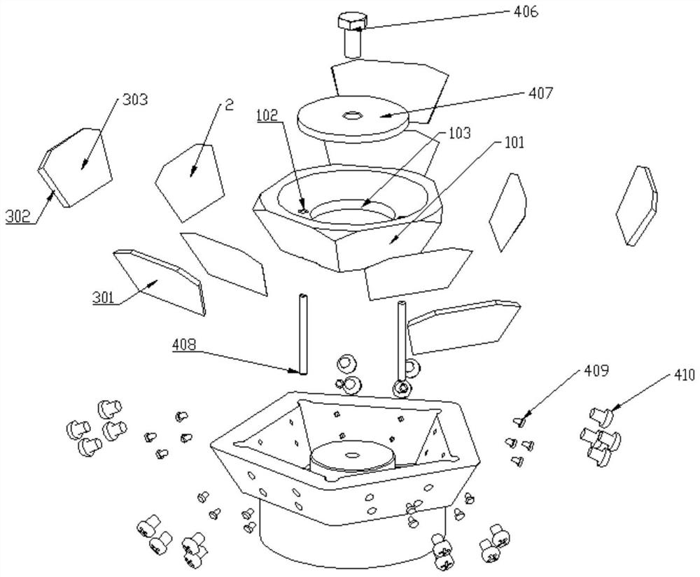
[0021] Such as figure 1 As shown, the patch-type multi-faceted mirror scanning system in this embodiment includes a base, a mirror, a soldering piece, and special tools for assisting welding.

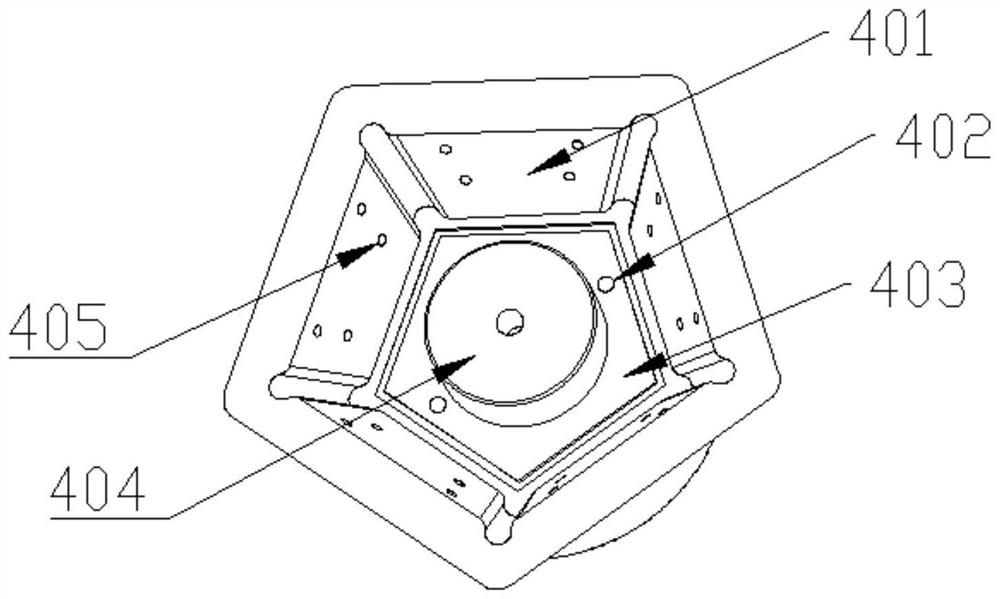
[0022] figure 1 Among them, number 1 is the base, including a positioning plane 101 , a positioning hole 102 and a mounting hole 103 . Among them, 101, the positioning plane 101 usually has a roughness of not more than 2 microns and a dyne value of not less than 28; the positioning hole 102 is used for positioning with the positioning rod 408 and the positioning hole 402 on the welding tool during welding. The mounting hole 103 is used for clearance fit with the positioning column 404 during welding, and is used for positioning; the mounting hole 103 is used for matching with the motor shaft (not shown in the figure) after welding to drive the base 1 ...


PUM

PropertyMeasurementUnit
Thicknessaaaaaaaaaa
Roughnessaaaaaaaaaa

Abstract

The invention discloses a patch type multi-surface rotating mirror scanning system and a manufacturing method, the scanning system comprises a base, a plurality of positioning planes are arranged on the side surface of the base, and reflectors are arranged on the positioning planes, and the patch type multi-surface rotating mirror scanning system is characterized in that the reflectors are welded and fixed on the positioning planes; the surface mount type multi-surface rotating mirror scanning system has the advantages that aiming at the problems of poor surface type, low angle precision and low reliability at high temperature and high rotating speed in the use process of the surface mount type multi-surface rotating mirror scanning system, the plurality of reflectors are simultaneously welded and fixed on the base in a welding manner, so that the production difficulty is reduced, the angle precision and good surface type can be ensured, and the production efficiency is improved. The reliability of the system is improved, the system can stably work in the high-temperature and high-rotating-speed environment, and large-scale production can be achieved.

Description

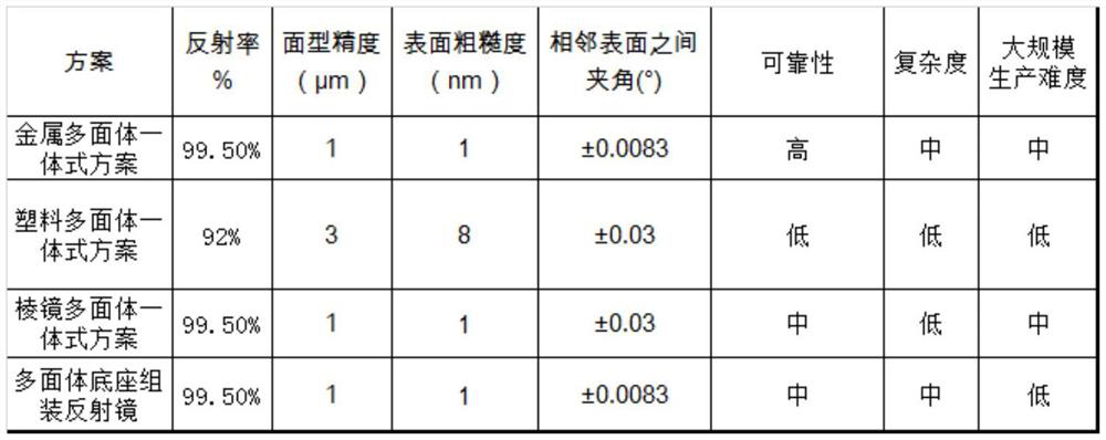
technical field [0001] The invention relates to an optical scanning system, in particular to a patch type multi-faceted rotating mirror scanning system and a manufacturing method thereof. Background technique [0002] In the fields of laser printing and lidar, the multi-faceted mirror scanning system is a core optical system. Driven by the rotation of the motor, the multi-faceted mirror can reflect the light emitted by the laser light source, scan the light to the subsequent beam expander system, and then hit the surface of the measured object. A part of the diffusely reflected light generated by the light on the measured object returns to the original path and is received by the detector. The distance of the measured object is calculated by half of the product of the light propagation time and the speed of light. [0003] At present, there are four mainstream schemes for polygonal mirror scanning systems, which are metal polyhedron integrated scheme, plastic polyhedron coa...

Claims


Application Information

Patent Timeline
IPC IPC(8): G01S7/481
CPCG01S7/4817
Inventor 崔志英杨勇姬凌喻军张丽芝李瑞王志扬
Owner NINGBO YONGXIN OPTICS
Learn More