Chemical adsorption instrument with function of removing residual gas in pipeline by vacuumizing

A residual gas and chemical adsorption technology, which is applied in the preparation of scientific instruments, instruments, and test samples, can solve problems such as pollution, slow diffusion, and impact on test accuracy, and achieve improved activation efficiency and high cleanliness Effect

Pending Publication Date: 2022-05-06
贝士德仪器科技(北京)有限公司
View PDF0 Cites 0 Cited by
  • Summary
  • Abstract
  • Description
  • Claims
  • Application Information

AI Technical Summary

Problems solved by technology

[0003] However, at present, there is a dead volume in the gas circulation pipeline of domestic and foreign chemical adsorption instruments. The dead volume refers to the fact that there is a branch pipeline connected to the main gas circulation pipeline, and one end of the branch pipeline is connected to the main pipeline and the other end is closed, which leads to The gas in the dead volume can only enter and leave the main pipe by diffusion, but the diffusion rate is very slow
Therefore, the reaction gas flowing in the main pipeline will be polluted by different gases remaining in the dead volume of the previous test, resulting in low purity of the test gas and affecting the accuracy of the test
[0004] In addition, before the sample is subjected to chemical adsorption test, activation pretreatment is required. At present, the activation method of the chemical adsorption instrument at home and abroad is: the heating furnace heats the sample while purging with inert gas. This activation method is inefficient and the activation The surface cleanliness of the sample is low

Method used


Image

  • Chemical adsorption instrument with function of removing residual gas in pipeline by vacuumizing

Examples


Embodiment Construction

[0019] The technical solutions in the embodiments of the present invention will be clearly and completely described below in conjunction with the accompanying drawings in the embodiments of the present invention. Obviously, the described embodiments are only some of the embodiments of the present invention, not all of them. Based on the embodiments of the present invention, all other embodiments obtained by persons of ordinary skill in the art without making creative efforts belong to the protection scope of the present invention.

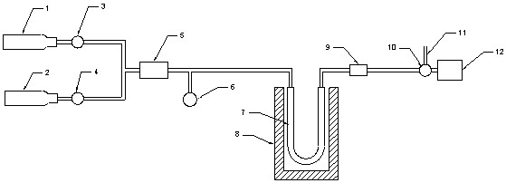
[0020] A chemical adsorption instrument with the function of vacuuming to remove residual gas in pipelines, comprising: a first gas source 1, a second gas source 2, a first stop valve 3, a second stop valve 4, a gas flow controller 5, and a pressure sensor 6. U-shaped sample tube 7, heating furnace 8, detector 9, two-position three-way valve 10, exhaust pipe 11, and vacuum pump 12.

[0021] The first gas source 1 is connected to the inlet of the fi...


PUM


Abstract

A chemical adsorption instrument with a function of removing residual gas in a pipeline through vacuumizing is characterized in that a first gas source is connected with an inlet of a first stop valve through a pipeline, a second gas source is connected with an inlet of a second stop valve through a pipeline, and outlets of the first stop valve and the second stop valve are connected with an inlet of a flow controller through pipelines; an outlet of the flow controller is connected with an inlet of the U-shaped sample pipe through a pipeline, an outlet of the U-shaped sample pipe is connected with an inlet of the detector through a pipeline, the inlet of the detector is connected with an inlet of the two-position three-way valve through a pipeline, and two outlets of the two-position three-way valve are connected with the vacuum pump and the exhaust pipe respectively. The whole gas path system is vacuumized through the vacuum pump, so that the influence of residual gas in dead volume of a pipeline on the test can be eliminated; meanwhile, the sample is subjected to activation pretreatment in a heating and vacuumizing manner, so that the activation efficiency can be improved, and the surface cleanliness of the sample is higher.

Description

technical field [0001] The application relates to the field of chemical adsorption instruments and equipment, in particular to a chemical adsorption instrument with the function of vacuuming and removing residual gas in pipelines. Background technique [0002] The chemical adsorption instrument mainly adopts the dynamic method for testing. The so-called dynamic method is to introduce flowing gas during the temperature-programming process of the sample. When the gas concentration changes, this concentration change is detected by the detector, and the reaction temperature, gas consumption, gas desorption and other information can be tested. In the above test process, the higher the gas purity, the better the accuracy of the test. [0003] However, at present, there is a dead volume in the gas circulation pipeline of domestic and foreign chemical adsorption instruments. The dead volume refers to the fact that there is a branch pipeline connected to the main gas circulation pip...

Claims


Application Information

Patent Timeline
IPC IPC(8): G01N30/00G01N1/24G01N1/40G01N1/44
CPCG01N30/00G01N1/24G01N1/405G01N1/44
Inventor 柳剑峰刘小虎
Owner 贝士德仪器科技(北京)有限公司
Why Eureka
Try Eureka