
Metal plate drilling equipment for intelligent workshop

A metal sheet and drilling equipment technology, applied in metal processing equipment, welding equipment, laser welding equipment and other directions, can solve the problems of sheet hole forming, impact, inconsistent upper and lower apertures, etc., to improve quality and reduce external factors. , to avoid the effect of resonance

Pending Publication Date: 2022-04-22
江苏双梦源精密成型科技有限公司
View PDF0 Cites 0 Cited by
  • Summary
  • Abstract
  • Description
  • Claims
  • Application Information

AI Technical Summary

Problems solved by technology

[0004] In the process of drilling metal sheets, laser drilling devices may be used. There are many types of laser equipment, but the fundamental principle is to apply laser beams of specific wavelengths to the processed objects. In industries where lasers are widely used In the field, laser is used as a tool for cutting, drilling or processing and engraving. The laser drilling process is a thermophysical process of interaction between laser and matter, which is determined by the characteristics of the laser beam and many thermophysical properties of the matter. Laser In the process of drilling, it is also necessary to pay attention to the relationship between laser energy, plate material and the gap distance between the laser and different plates. Simply put, the same laser energy needs to be adjusted differently for different plate materials. In order to avoid the inconsistency of the upper and lower hole diameters of the plate, in today’s laser drilling equipment, while considering the laser focal length, the impact of the laser on the processing should also be considered, which will lead to the formation of the plate. hole effect problem

Method used


Image

  • Metal plate drilling equipment for intelligent workshop
  • Metal plate drilling equipment for intelligent workshop
  • Metal plate drilling equipment for intelligent workshop

Examples


Embodiment Construction

[0035] In order to make the objects and advantages of the present invention clearer, the present invention will be specifically described below in conjunction with examples. It should be understood that the following words are only used to describe one or several specific implementation modes of the present invention, and do not strictly limit the protection scope of the specific claims of the present invention.

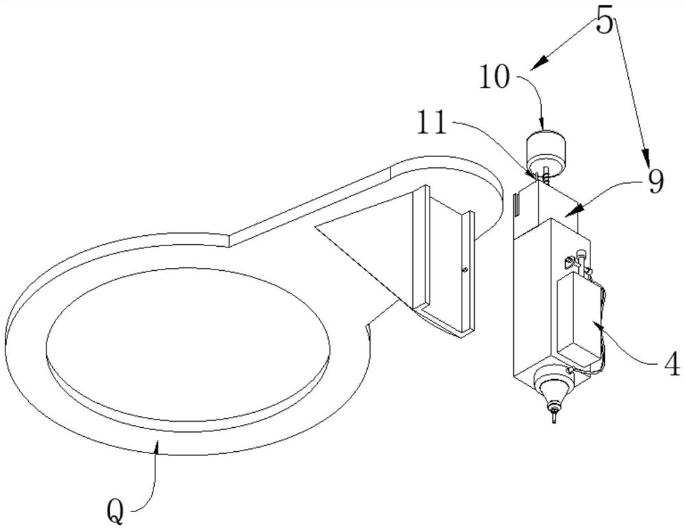
[0036] see Figure 1-11 , a sheet metal drilling equipment for an intelligent workshop, comprising a beam 1, a stroke arm 2 slidably mounted on the bottom of the beam 1, and a working machine tool 3 installed corresponding to the stroke arm 2, the bottom end of the stroke arm 2 can be A laser part 4 for hole extraction is provided in rotation, and a focusing mechanism 5 is provided on the top of the laser part 4 .

[0037] The top of the machine tool 3 is hollow and extends the chamber 6 provided inside. The inner cavity of the machine tool 3 is provided with a sink...


PUM


Abstract

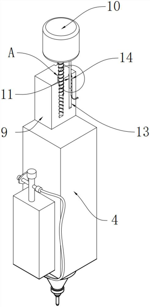
The invention discloses metal plate drilling equipment for an intelligent workshop, and belongs to the field of drilling equipment, the metal plate drilling equipment comprises a cross beam, a stroke machine arm slidably mounted at the bottom of the cross beam, and a working machine tool mounted corresponding to the stroke machine arm, the bottom end of the stroke machine arm is rotatably provided with a laser part used for drilling, and the top of the laser part is provided with a focusing mechanism; the top of the working machine tool is hollow and extends to form a cavity, a sinking and pressing mechanism and a jacking and supporting mechanism are arranged on the upper portion and the lower portion of the cavity of the working machine tool, and the focusing mechanism comprises a bearing block arranged on the top of the laser part and a lead screw stepping motor located above the bearing block; a lead screw on the lead screw stepping motor vertically extends into the bearing block to be in threaded driving connection with the bearing block, and a touch guide rod is further arranged at the bottom of the lead screw stepping motor, so that the influence of the defocusing effect on hole forming of the metal plate can be reduced, the focusing precision between laser and the metal plate is improved, and the hole forming quality is improved.

Description

technical field [0001] The invention relates to the field of drilling equipment, and more specifically relates to a metal plate drilling equipment for an intelligent workshop. Background technique [0002] Generally speaking, the metal sheet is a sheet made of metal, and the metal sheet also has a sheet made of precious metal. [0003] The precious metals mainly refer to gold, silver and platinum group metals (ruthenium, rhodium, palladium, osmium, iridium, platinum) and other 8 kinds of metal elements; most of these metals have beautiful color and strong chemical stability. It is not easy to chemically react with other chemical substances, but with the development of technological progress, precious metals and one or more different types of compatible materials are physically synthesized with multi-phase structure precious metal materials, precious metal materials have the same properties as precious metals Similar characteristics, such as good electrical conductivity and ...

Claims


Application Information

Patent Timeline
Patent Type & Authority Applications(China)
IPC IPC(8): B23K26/382B23K26/08B23K26/70
CPCB23K26/382B23K26/0884B23K26/702
Inventor 许应龙吉敏祥
Owner 江苏双梦源精密成型科技有限公司
Learn More