Heavy-duty gear capable of improving bearing capacity of lubricating oil film
A technology of bearing capacity and lubricating oil film, applied in the directions of gear lubrication/cooling, belt/chain/gear, gear vibration/noise attenuation, etc., can solve the thermal characteristics change, the coating is easy to fall off, and it is impossible to take into account the multiple performance integration of gear meshing transmission. optimization and other issues to achieve the effects of reducing frictional vibration, reducing energy accumulation on the tooth surface, reducing energy accumulation and frictional vibration on the tooth surface
- Summary
- Abstract
- Description
- Claims
- Application Information
AI Technical Summary
Problems solved by technology
Method used
Image
Examples
Embodiment 1
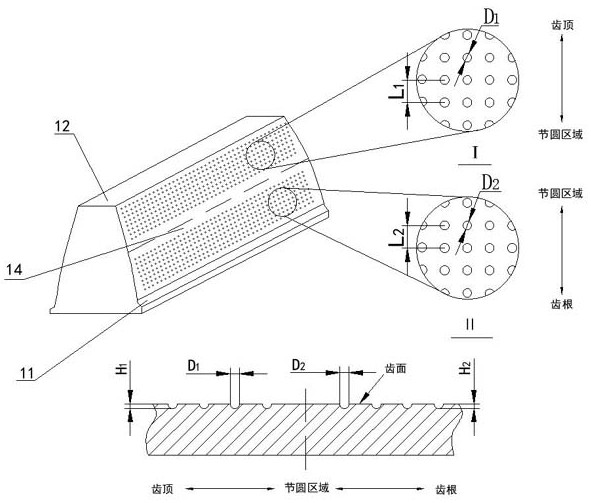
[0040] Such as figure 2 As shown, the outline where the pit 2 intersects with the tooth surface 13 is a circle. The distance between the two adjacent upper pits 21 is L 1 , the distance between the two adjacent lower pits 22 is L 2 , the L 1 with L 2 Equivalently, its range is 400-800 μm.
[0041] The contour projected diameter of the intersection of the upper dimple 21 and the tooth surface 13 is D 1 , the depth from the tooth surface 13 to the bottom of the upper pit 21 is H 1 ; The contour projected diameter of the intersection of the lower pit 22 and the tooth surface 13 is D 2 , the depth from the tooth surface 13 to the bottom of the lower pit 22 is H 2 ; the D 1 with D 2 equal, its range is 50-100μm; the H 1 with H 2 Equivalently, its range is 10-50 μm.
Embodiment 2
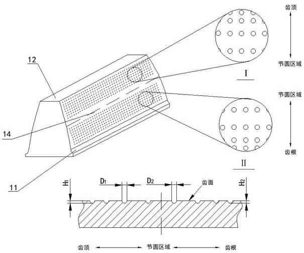
[0043] Such as image 3 As shown, the distance between the adjacent rows of the upper dimples 21 gradually decreases from the pitch circle area 14 to the tooth top 12; the minimum distance L between the rows of the upper dimples 21 is min 400μm, maximum L max is 800μm, and its gradient value is divided by the maximum difference of the pitch divided by the gradient amount;
[0044] The distance between the adjacent rows of the lower dimples 22 gradually decreases from the pitch circle area 14 to the dedendum 11; the minimum distance L between the rows of the lower dimples 22 is min 400μm, maximum L max It is 800μm, and its change gradient value is divided by the maximum difference of the pitch divided by the gradient amount.
Embodiment 3
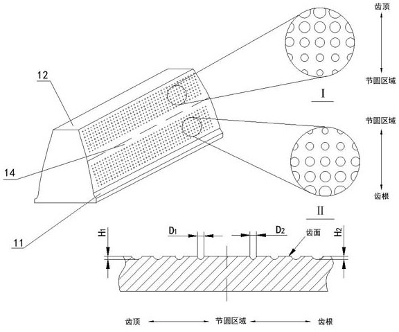
[0046] Such as Figure 4 As shown, the diameter of the upper dimple 21 gradually increases from the pitch circle area 14 to the contour projection diameter of the adjacent rows intersecting the tooth surface 13 in the direction of the tooth top 12; the lower dimple 22 gradually increases from the pitch circle area 14 to The minimum diameter D of the contour projection intersecting the tooth surface 13 between adjacent rows in the direction of the tooth root 11 min 50μm, the largest diameter D max is 100μm, and its change gradient value is the maximum difference of the diameter divided by the gradient amount;
[0047] The projected diameter of the lower dimple 22 gradually increases from the pitch circle area 14 to the dedendum 11. The minimum diameter D of the contour projection intersecting the tooth surface 13 between adjacent rows min 50μm, the largest diameter D max is 100μm, and its change gradient value is the maximum difference of the diameter divided by the gradien...
PUM
 Abstract
Description
Claims
Application Information
 - Generate Ideas
- Intellectual Property
- Life Sciences
- Materials
- Tech Scout
- Unparalleled Data Quality
- Higher Quality Content
- 60% Fewer Hallucinations
Browse by: Latest US Patents, China's latest patents, Technical Efficacy Thesaurus, Application Domain, Technology Topic, Popular Technical Reports.
© 2025 PatSnap. All rights reserved.Legal|Privacy policy|Modern Slavery Act Transparency Statement|Sitemap|About US| Contact US: help@patsnap.com


