Liquid nitrogen drainage device, liquid nitrogen drainage method and chip testing system

A technology of liquid nitrogen drainage device and liquid nitrogen, which is applied in the field of liquid nitrogen drainage device and chip test system, which can solve the problems of slow liquid drainage speed and inability to recover liquid nitrogen reasonably and effectively, so as to reduce the gasification rate and improve the effective utilization rate , The effect of improving test efficiency

Pending Publication Date: 2022-04-05
BEIJING SEMICON EQUIP INST THE 45TH RES INST OF CETC
View PDF2 Cites 0 Cited by
  • Summary
  • Abstract
  • Description
  • Claims
  • Application Information

AI Technical Summary

Problems solved by technology

[0004] The invention provides a liquid nitrogen drainage device to solve the technical problems in the prior art that the gasification of the liquid nitrogen is serious when the liquid nitrogen is discharged, causing the liquid nitrogen to leak slowly and the liquid nitrogen cannot be recovered reasonably and effectively, so as to realize part of the process of chip testing. Rapid discharge and recovery of all liquid nitrogen after liquid nitrogen and chip testing, improve chip testing efficiency and effective utilization of liquid nitrogen, and avoid low temperature damage caused by liquid nitrogen leakage

Method used


Image

  • Liquid nitrogen drainage device, liquid nitrogen drainage method and chip testing system
  • Liquid nitrogen drainage device, liquid nitrogen drainage method and chip testing system
  • Liquid nitrogen drainage device, liquid nitrogen drainage method and chip testing system

Examples


Embodiment Construction

[0046] Exemplary embodiments of the present invention will be described in more detail below with reference to the accompanying drawings. Although exemplary embodiments of the present invention are shown in the drawings, it should be understood that the invention may be embodied in various forms and should not be limited to the embodiments set forth herein. Rather, these embodiments are provided for more thorough understanding of the present invention and to fully convey the scope of the present invention to those skilled in the art.

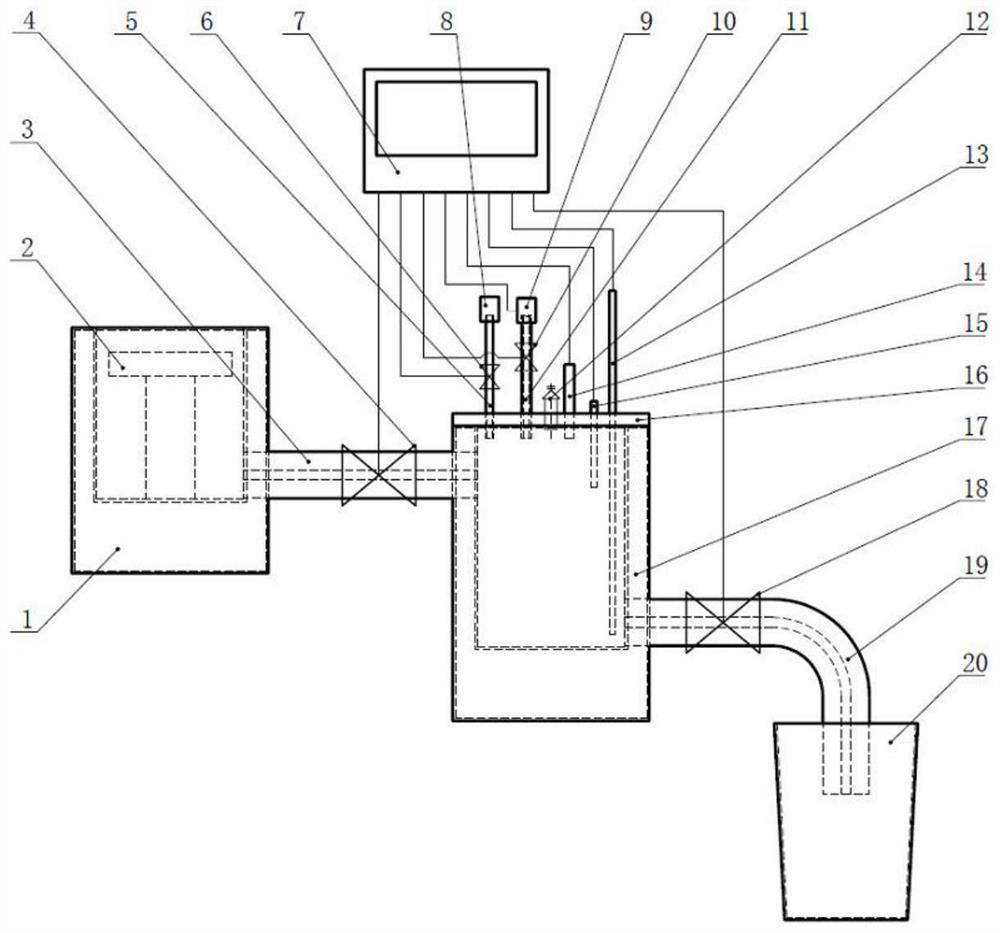
[0047] The embodiment of the present invention provides a liquid nitrogen discharge device, such as figure 1As shown, it includes a first Dewar 1 , a second Dewar 17 , a first discharge pipe 3 , a first solenoid valve 4 , a liquid level gauge 13 and a control module 7 .

[0048] The first Dewar 1 is not sealed, and uses liquid nitrogen to provide a low-temperature environment, and a wafer platform 2 is arranged therein, and the wafer platform 2...


PUM


Abstract

The invention discloses a liquid nitrogen drainage device, a liquid nitrogen drainage method and a chip testing system. The liquid nitrogen drainage device comprises a first Dewar which is not sealed, provides a low-temperature environment by using liquid nitrogen, is internally provided with a chip bearing table for bearing a chip to be tested, and is connected with a second Dewar through a first drainage pipe, and the height of the first drainage pipe is lower than that of the chip bearing table; a first electromagnetic valve is arranged on the first liquid discharge pipe; the first electromagnetic valve is connected with the control module and is opened or closed according to a control signal of the control module so as to start or stop discharging the liquid nitrogen in the first Dewar into the second Dewar; the second Dewar flask is sealed through an end cover, a liquid level meter is arranged on the end cover, the input end of the liquid level meter is close to the bottom of the second Dewar flask, and the liquid level meter is connected with the control module. According to the liquid nitrogen drainage device, the liquid nitrogen in the first Dewar is recycled after the low-temperature test on the chip is finished, the chip test efficiency and the effective utilization rate of the liquid nitrogen are improved, and low-temperature damage caused by liquid nitrogen leakage is avoided.

Description

technical field [0001] The invention relates to the technical field of chip testing, in particular to a liquid nitrogen drainage device, a liquid nitrogen drainage method and a chip testing system. Background technique [0002] During the chip testing process, liquid nitrogen fluid is used to provide a controlled ultra-low temperature test environment for the device under test. The chip test system realizes the testing of chip electrical performance parameters through the physical contact between the probe tip and the chip pad. The test process requirement that the chip is immersed in the liquid nitrogen fluid determines that the liquid nitrogen container has an open structure. When the chip test system is working, the chip to be tested is placed on the wafer support set in the liquid nitrogen container. According to the process requirements, part of the liquid nitrogen needs to be discharged during chip loading / unloading operations to reduce the liquid nitrogen level and en...

Claims


Application Information

Patent Timeline
IPC IPC(8): B01L7/00F25D3/10F25D29/00G01R31/28
CPCY02P70/50
Inventor 贾月明陈占杰许向阳孙皓熙
Owner BEIJING SEMICON EQUIP INST THE 45TH RES INST OF CETC
Why Eureka
Try Eureka