Waste heat recovery device for engine

A waste heat recovery device and waste heat recovery technology, applied in engine components, combustion engines, machines/engines, etc., can solve the problems of rapid gasification, excessive temperature, explosion of waste heat recovery devices, etc., to reduce the gasification speed, prevent Excessive water vapor pressure, cost-saving effect

Pending Publication Date: 2019-09-24
PETROCHINA CO LTD
View PDF3 Cites 0 Cited by
  • Summary
  • Abstract
  • Description
  • Claims
  • Application Information

AI Technical Summary

Problems solved by technology

[0005] When the equipment downstream of the waste heat recovery device breaks down (such as the pump connected to the drain port of the waste heat recovery body) and the cold water in the waste heat recovery body stops flowing, the temperature in the waste heat recovery body is too high, resulting in Rapid gasification of the cooling water will cause safety accidents such as explosion of the waste heat recovery device

Method used


Image

  • Waste heat recovery device for engine
  • Waste heat recovery device for engine
  • Waste heat recovery device for engine

Examples


Embodiment Construction

[0053] In order to make the object, technical solution and advantages of the present invention clearer, the implementation manner of the present invention will be further described in detail below in conjunction with the accompanying drawings.

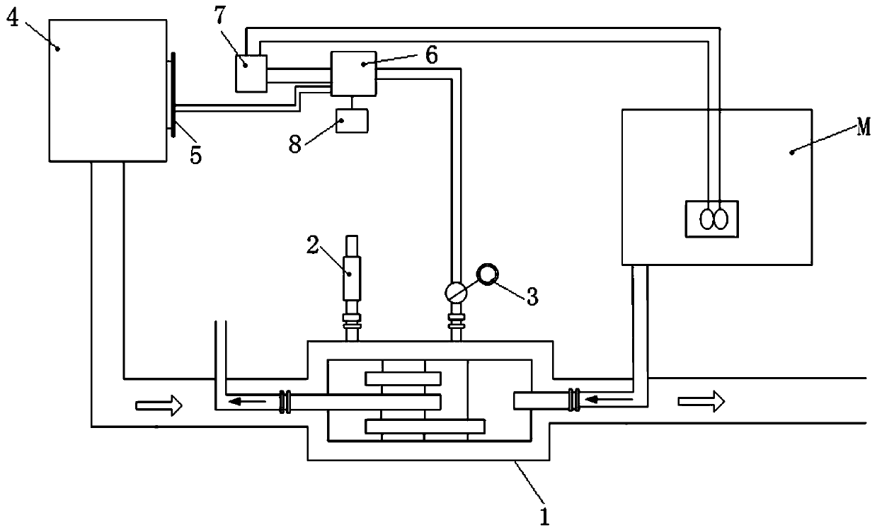
[0054] The embodiment of the present invention provides a waste heat recovery device for an engine, such as the attached figure 1As shown, the waste heat recovery device includes: a waste heat recovery body 1, a safety valve 2, a temperature sensor 3, a solenoid valve, a pressure sensor respectively arranged on the waste heat recovery body 1, a cooling circulating water tank 4, and a cooling circulating water tank 4. The liquid level sensor 5, the controller 6 electrically coupled with the temperature sensor 3, the liquid level sensor 5, the solenoid valve, and the pressure sensor, the relay 7 electrically coupled with the controller 6 and the engine M; The gas port is used to communicate with the exhaust port of the engine M, and the ...


PUM


Abstract

The invention discloses a waste heat recovery device for an engine, and belongs to the technical field of waste heat recovery. The waste heat recovery device comprises a waste heat recovery main body, a safety valve, a temperature sensor, a cooling circulation water tank, a liquid level sensor, a controller and a relay. According to the waste heat recovery device, in the case that a water vapor pressure in the waste heat recovery main body exceeds a first preset pressure due to the fault of the engine, pressure relief is carried out on the waste heat recovery main body by virtue of the safety valve; in the case that the temperature of the waste heat recovery main body exceeds the first preset pressure or the liquid level of the cooling circulation water tank is lower than a first preset liquid level due to the fault of the engine, an alarm signal is sent to terminal equipment by virtue of the controller, so that operating personnel can be guaranteed to grasp the working state of the waste heat recovery device in time; and in the case that the temperature of the waste heat recovery main body exceeds a second preset pressure or the liquid level of the cooling circulation water tank is lower than a second preset liquid level, the engine can be enabled to stop working through the cooperation of the controller and the relay, so that the waste heat recovery main body can be effectively prevented from being exploded.

Description

technical field [0001] The invention relates to the technical field of waste heat recovery, in particular to a waste heat recovery device for an engine. Background technique [0002] The engine will generate a lot of heat during operation. If it is discharged directly, it will cause a great waste of energy. Therefore, it is necessary to install a waste heat recovery device at the exhaust port of the engine. [0003] The current waste heat recovery device generally includes: a waste heat recovery body connected to the exhaust port of the engine, and the waste heat recovery body recovers waste heat through cold water heat exchange. [0004] The inventor finds that the prior art has at least the following problems: [0005] When the equipment downstream of the waste heat recovery device breaks down (such as the pump connected to the drain port of the waste heat recovery body) and the cold water in the waste heat recovery body stops flowing, the temperature in the waste heat re...

Claims


Application Information

Patent Timeline
IPC IPC(8): F01N5/02F28D21/00F28F27/00
CPCF01N5/02F28D21/00F28F27/00Y02T10/12
Inventor 闻伟刘志虎高李颖贾新明李雄师文嵩祁长海祁宝萍张金霞
Owner PETROCHINA CO LTD
Why Eureka
Try Eureka