Template passivation process
A template and process technology, which is applied in the field of template passivation technology, can solve the problems of non-densification and uneven passivation of the template surface, and achieve the effects of uniform and dense passivation, good demoulding effect, and good passivation effect
- Summary
- Abstract
- Description
- Claims
- Application Information
AI Technical Summary
Problems solved by technology
Method used
Image


Examples
Embodiment 1
[0067] The embodiment of the present application provides a template passivation process, including the following steps:
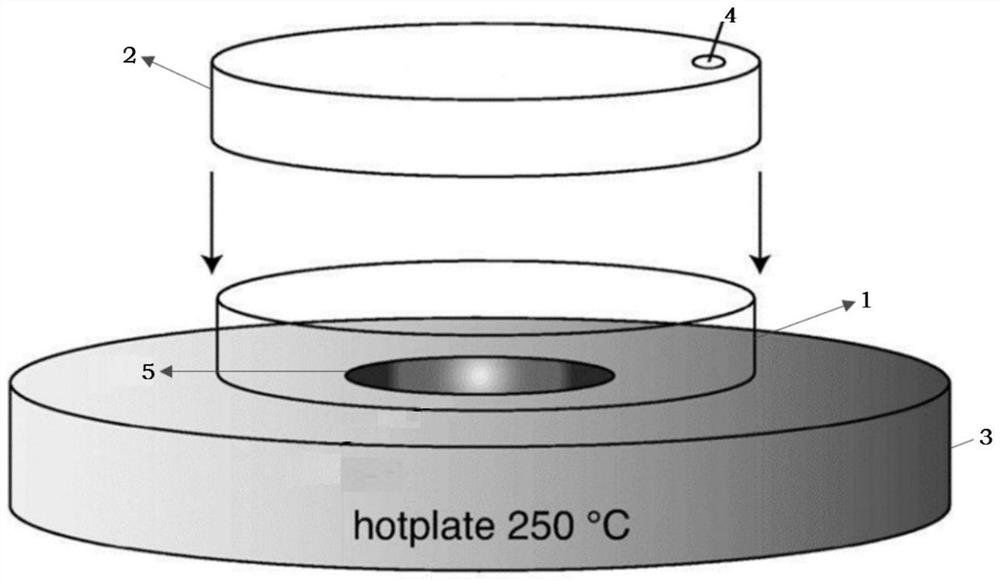
[0068] 1. Perform plasma treatment on the etched template for 5 minutes, place the processed template in the passivation chamber of the lower watch, and cover the upper watch on the lower watch, so that the upper watch and the lower watch form an airtight The atmosphere space, the atmosphere space includes the passivation chamber and the gasification chamber connected to each other;
[0069] 2. Use a pipette to pipette 25 μL of F13-TCS (trichloro(1H,1H,2H,2H-tridecafluoro-n-octyl)silane and inject it into the gasification chamber from the injection hole, and seal the injection hole with a stopper , F13-TCS drops onto the bottom plate of the gasification chamber;
[0070] 3. Start the heat conduction plate, the heat conduction plate heats the bottom plate of the lower surface dish at a heating rate of 10°C / min, so that the temperature of the bottom plate o...
Embodiment 2
[0074] The embodiment of the present application provides a template passivation process, including the following steps:
[0075] 1. Perform plasma treatment on the etched template for 5 minutes, place the processed template in the passivation chamber of the lower watch, and cover the upper watch on the lower watch, so that the upper watch and the lower watch form an airtight The atmosphere space, the atmosphere space includes the passivation chamber and the gasification chamber connected to each other;
[0076]2. Use a pipette to pipette 25 μL of F13-TCS (trichloro(1H,1H,2H,2H-tridecafluoro-n-octyl)silane and inject it into the gasification chamber from the injection hole, and seal the injection hole with a stopper , F13-TCS drops onto the bottom plate of the gasification chamber;
[0077] 3. Start the heat conduction plate, the heat conduction plate heats the bottom plate of the lower surface dish at a heating rate of 10°C / min, so that the temperature of the bottom plate of...
Embodiment 3
[0080] The embodiment of the present application provides a template passivation process, including the following steps:
[0081] 1. Perform plasma treatment on the etched template for 5 minutes, place the processed template in the passivation chamber of the lower watch, and cover the upper watch on the lower watch, so that the upper watch and the lower watch form an airtight The atmosphere space, the atmosphere space includes the passivation chamber and the gasification chamber connected to each other;
[0082] 2. Use a pipette to pipette 25 μL of 1H, 1H, 2H, 2H-perfluorodecyltrichlorosilane to inject from the injection hole into the vaporization chamber, and seal the injection hole with a stopper, 1H, 1H, 2H, 2H - Perfluorodecyltrichlorosilane dripping onto the bottom plate of the vaporization chamber;
[0083] 3. Start the heat conduction plate, the heat conduction plate heats the bottom plate of the lower surface dish at a heating rate of 10°C / min, so that the temperature...
PUM
 Abstract
Description
Claims
Application Information
 - R&D
- Intellectual Property
- Life Sciences
- Materials
- Tech Scout
- Unparalleled Data Quality
- Higher Quality Content
- 60% Fewer Hallucinations
Browse by: Latest US Patents, China's latest patents, Technical Efficacy Thesaurus, Application Domain, Technology Topic, Popular Technical Reports.
© 2025 PatSnap. All rights reserved.Legal|Privacy policy|Modern Slavery Act Transparency Statement|Sitemap|About US| Contact US: help@patsnap.com