Degassing device and method for power electronic cooling system

A technology of cooling system and power electronics, applied in separation methods, chemical instruments and methods, liquid degassing, etc., can solve the problems of long operation time, low degassing efficiency, waste of time, etc., and achieve increased contact area, degassing Good effect and high efficiency

Pending Publication Date: 2022-04-01
GUANGZHOU GOALAND ENERGY CONSERVATION TECH
View PDF0 Cites 0 Cited by
  • Summary
  • Abstract
  • Description
  • Claims
  • Application Information

AI Technical Summary

Problems solved by technology

This kind of device consumes a lot of gas and takes a long time to operate. To meet the gas content requirements of a conventional HVDC converter valve cooling system, it needs to consume more than 200 bottles of nitrogen (each bottle is 40L), and it takes more than 30 days.
This solution consumes nitrogen, wastes time, and has low degassing efficiency

Method used


Image

  • Degassing device and method for power electronic cooling system

Examples


Embodiment Construction

[0030] The application will be further described below in conjunction with the accompanying drawings. The following examples are only used to illustrate the technical solutions of the present invention more clearly, but not to limit the protection scope of the present application.

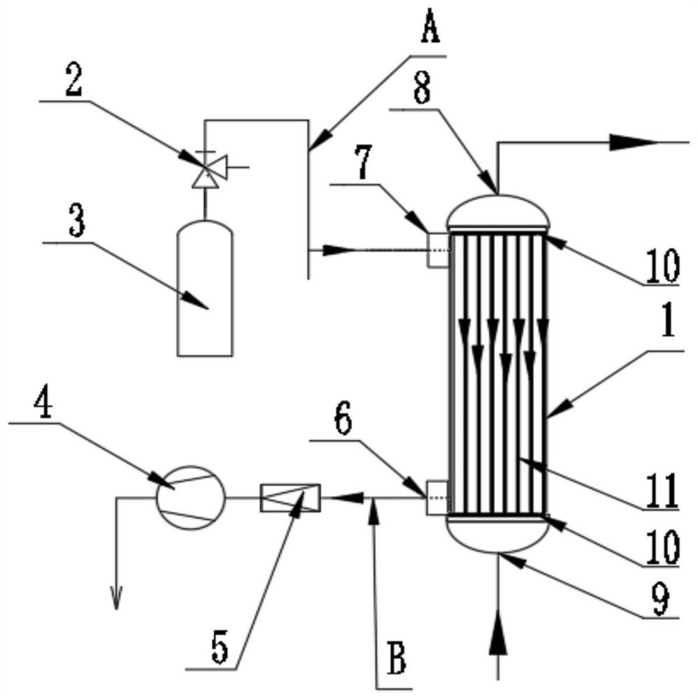
[0031] Usually, the gas in the gas storage tank is directly released into the liquid. The present disclosure utilizes the hollow fiber 11 in the degassing membrane tube for degassing. The contact area with the liquid is larger, and the gas in the liquid is removed faster and more effectively.

[0032] like figure 1 shown. The degassing membrane tube 1 includes hollow fiber filaments 11 inside. The inside of the hollow fiber 11 is used to remove gas, and the liquid to be degassed in the degassing membrane tube 1 is outside the hollow fiber 11 . The two ends of the degassing film tube 1 have a liquid inlet 9 and a liquid outlet 8, and the sides near the two ends have an air inlet 7 and an air outl...


PUM


Abstract

A degassing device of a power electronic cooling system comprises a degassing film pipe and a negative pressure generating device, the degassing film pipe is provided with a liquid inlet and a liquid outlet and used for degassing liquid, and the degassing device is characterized in that a hollow degassing material is arranged in the degassing film pipe and can permeate gas but cannot permeate liquid; the degassing membrane tube is provided with a gas inlet and a gas outlet, and the two ends of the hollow degassing material are connected to the gas inlet and the gas outlet respectively; and the negative pressure generating device is used for generating negative pressure in the hollow degassing material. The method has the beneficial effects that the consumption of nitrogen is reduced, the degassing time is shortened, and the efficiency is relatively high; and the contact area with liquid is increased through the hollow degassing material, so that the degassing effect is good.

Description

technical field [0001] The invention belongs to the field of cooling system degassing, and more specifically relates to a degassing device and method for a power electronic cooling system. Background technique [0002] In the related technology, the valve cooling system mainly consumes high-purity nitrogen (99.99%) and uses micro-holes to continuously blow nitrogen at the bottom of the expansion tank, and the gas (mainly oxygen) in the circulating water is brought out of the circulation through the gas path on the expansion tank. system to meet the requirements of reducing the gas content in the circulation system medium. [0003] The bottom of the expansion tank is connected to the nitrogen cylinder and has a blowing pipe. When the valve cooling system is running, nitrogen gas enters from the bottom, blows at high pressure, squeezes the gas content in the system liquid, and reduces the system liquid gas content. This kind of device consumes a lot of gas and takes a long t...

Claims


Application Information

Patent Timeline
Patent Type & Authority Applications(China)
IPC IPC(8): B01D19/00
Inventor 崔鹏飞代飞马根坡丘淼生
Owner GUANGZHOU GOALAND ENERGY CONSERVATION TECH
Why Eureka
Try Eureka