Hybrid multi-level converter control method based on open-loop common-mode voltage injection
A multi-level converter, common mode voltage technology, applied in the direction of converting AC power input to DC power output, electrical components, output power conversion devices, etc., can solve the large voltage fluctuations of DC bus side capacitors and flying capacitors and other problems, to achieve the effect of suppressing capacitor voltage fluctuations, reducing complexity and cost, and enhancing the ability to operate safely and reliably
- Summary
- Abstract
- Description
- Claims
- Application Information
AI Technical Summary
Problems solved by technology
Method used
Image
Examples
Embodiment 1
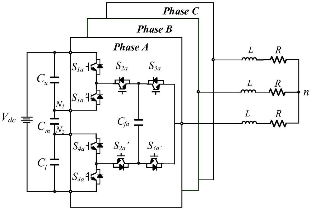
[0028] Such as figure 1 Shown is a schematic diagram of the inverter circuit connection of the three-phase four-level HCC, in which, including the DC power supply V dc , a hybrid multilevel converter (HCC) and a load RL;
[0029] DC power V dc , used to provide DC power supply voltage, the voltage level is between 100V and 15kV;
[0030] The hybrid multilevel converter includes DC bus side capacitor C u 、C m 、C l , the flying capacitor C fn (n=a, b, c) and four bridge arms;
[0031] DC bus terminal capacitance C u 、C m and C l connected in series;
[0032] DC power V dc The positive electrode of the hybrid multilevel converter and the DC bus terminal capacitor C u connected to the anode of V dc The negative electrode of the hybrid multilevel converter and the DC terminal capacitor C l connected to the negative pole and grounded reliably;
[0033] The four bridge arms include four sets of main switches, namely S 1n and S' 1n , S 2n and S' 2n , S 3n and S' 3...
Embodiment 2
[0047] Such as figure 1 Shown is a schematic diagram of the inverter circuit connection of the three-phase four-level HCC, in which, including the DC power supply V dc , a hybrid multilevel converter (HCC) and a load RL;
[0048] DC power V dc , used to provide DC power supply voltage, the voltage is 6kV;
[0049] DC bus side capacitance C u 、C m 、C l and flying capacitor C fn The capacitance value is 0.1mF;
[0050] The three-phase load consists of three series connected resistors and inductors. The resistance of the load RL resistor is 10Ω, and the inductance is 5mH;
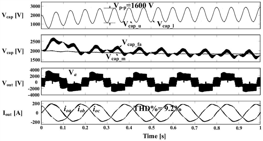
[0051] The HCC system modulation ratio is set to 0.6, and the working frequency is 5Hz;
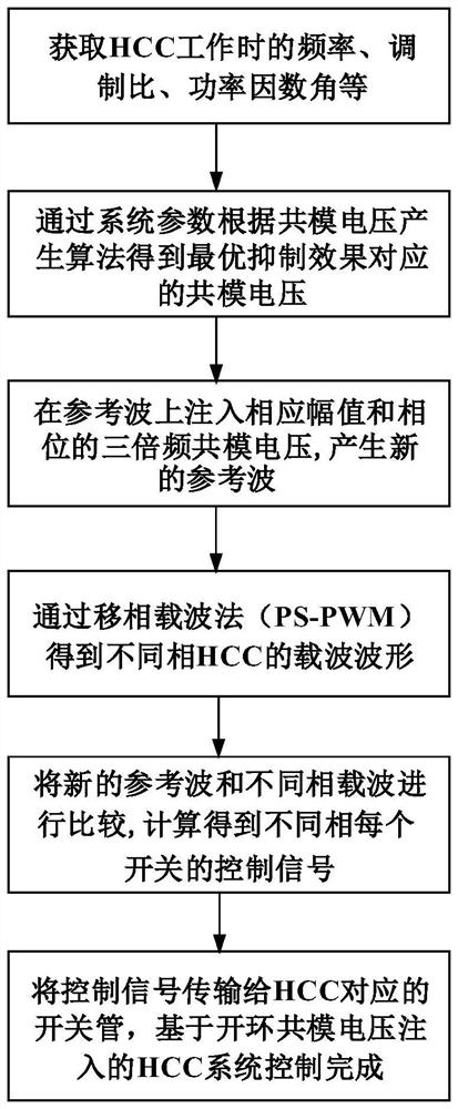
[0052] The HCC capacitor voltage fluctuation control method based on open-loop common-mode voltage injection in this embodiment is as follows: figure 2 As shown, the specific steps are as follows:
[0053] (1) When the three-phase four-level HCC system works normally, the three-phase modulation wave V ref_a , ...
PUM
 Abstract
Description
Claims
Application Information
 - R&D
- Intellectual Property
- Life Sciences
- Materials
- Tech Scout
- Unparalleled Data Quality
- Higher Quality Content
- 60% Fewer Hallucinations
Browse by: Latest US Patents, China's latest patents, Technical Efficacy Thesaurus, Application Domain, Technology Topic, Popular Technical Reports.
© 2025 PatSnap. All rights reserved.Legal|Privacy policy|Modern Slavery Act Transparency Statement|Sitemap|About US| Contact US: help@patsnap.com


