Efficient water and electricity cogeneration device

A hydropower and high-efficiency technology, applied in the field of solar thermal, can solve the problems of speeding up the utilization cycle of pure water, salt formation on the surface of photothermal materials, blockage of pores, etc. Effect

Active Publication Date: 2022-03-22
GUILIN UNIV OF ELECTRONIC TECH
View PDF3 Cites 0 Cited by
  • Summary
  • Abstract
  • Description
  • Claims
  • Application Information

AI Technical Summary

Problems solved by technology

[0005] The purpose of the present invention is to overcome the deficiencies of the prior art, and provide a solar steam device for hydropower cogeneration, which reduces the conduction heat loss of the direct contact between the photothermal material and the water body, and solves the problem of salt formation on the surface of the photothermal material and channel blockage problems, self-generated electricity can be directly used for quality monitoring of purified water, which speeds up the utilization cycle of purified water

Method used


Image

  • Efficient water and electricity cogeneration device
  • Efficient water and electricity cogeneration device
  • Efficient water and electricity cogeneration device

Examples


Embodiment 1

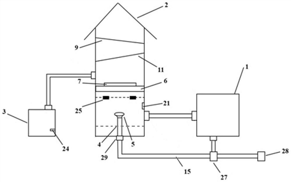
[0051] The action time of the shower is controlled according to the set temperature threshold. When the temperature of the cold end reaches or exceeds the temperature threshold, the main controller 17 controls the closing of the relay 19 in the normally open state, thereby controlling the solenoid valve 27 to open and the liquid to be treated Spray on the CS / PVA airgel 23 from bottom to top through the shower, exchange heat with the cold end of the thermoelectric sheet 7, reduce the temperature of the cold end, and generate electricity. When the temperature of the cold end is lower than the temperature threshold, the water supply device stops spraying water. At the same time, the temperature of the liquid to be treated rises, which can accelerate the generation of steam. The analog-to-digital converter 18 digitizes the information collected by the patch thermocouple, the OLED board 20 visualizes the collected temperature, and the relay 19 is connected with the solenoid valve 27...

Embodiment 2

[0053] Referring to Embodiment 1, the difference is that the action time of the shower is controlled according to the set duration. When the power is turned on, the main controller 17 controls the closing of the relay 19 in the normally open state, thereby controlling the opening of the solenoid valve 27. The liquid to be treated is sprayed on the CS / PVA airgel 23 from bottom to top through the shower, and exchanges heat with the cold end of the thermoelectric sheet 7, reduces the temperature of the cold end, and generates electric energy. After the set duration is over, the water supply device stops Spraying water while increasing the temperature of the liquid to be treated accelerates the generation of steam. The analog-to-digital converter 18 digitizes the information collected by the patch thermocouple, the OLED board 20 visualizes the collected temperature, and the relay 19 is connected with the solenoid valve 27 to control the on-off of the solenoid valve 27 .

[0054] T...


PUM


Abstract

The invention provides an efficient water and electricity co-production device which comprises a hardware box, a water and electricity co-production chamber and a purified water storage box, a water and electricity co-production module is arranged in the water and electricity co-production chamber and comprises a plurality of water and electricity co-production units, each water and electricity co-production unit comprises a thermoelectric piece, a blue film and CS/PVA aerogel, the blue film is attached to the hot end of the thermoelectric piece, and the CS/PVA aerogel is attached to the hot end of the thermoelectric piece. The cold end of the thermoelectric piece is provided with CS/PVA aerogel, the hot end of the thermoelectric piece faces upwards, the cold end of the thermoelectric piece faces downwards, the shower nozzle sprays water to the water and electricity cogeneration module from bottom to top, the blue film absorbs solar energy, then heat energy is transmitted to the CS/PVA aerogel through the thermoelectric piece, water to be evaporated is provided for the CS/PVA aerogel in a spraying water supply mode, and the water to be evaporated is evaporated through the temperature difference between the two ends of the thermoelectric piece. Purified water and electric energy can be generated simultaneously; the jet water supply mode not only can increase the output of purified water and electric energy of the water and electricity cogeneration module, but also can solve the problems of surface salt deposition, pore channel blockage and the like of the photo-thermal material.

Description

technical field [0001] The invention belongs to the field of solar photothermal technology, and in particular relates to a high-efficiency hydroelectric cogeneration device. Background technique [0002] With the rapid development of modern social economy and human civilization, the use of a series of non-renewable energy sources (such as: coal, oil, etc.) has been greatly enhanced, the problem of energy shortage has become increasingly prominent, and the price has risen sharply. At the same time, during the utilization of fossil fuels, harmful gases, inhalable particles and solid wastes are produced that seriously affect the natural environment and hinder the further improvement of human life quality. Therefore, seeking a renewable, non-polluting and clean energy has become a current research hotspot, which is closely related to the concept of "sustainable development". [0003] As the "source of omnipotence", solar energy is an inexhaustible clean energy source, and the t...

Claims


Application Information

Patent Timeline
Patent Type & Authority Applications(China)
IPC IPC(8): C02F1/14F24S10/00F22B1/28F22B1/00G01N33/18
CPCC02F1/14F24S10/00F22B1/28F22B1/00G01N33/18Y02E10/44Y02A20/124Y02A20/142Y02A20/212
Inventor 苗蕾穆晓江魏安涢周建华刘静田永芝
Owner GUILIN UNIV OF ELECTRONIC TECH
Why Eureka
Try Eureka