
Double-stop-band frequency selective surface structure with high resonance ratio and unit structure

A frequency selective surface, unit structure technology, applied in the field of electromagnetic waves, can solve the problems of high overall structure thickness, poor structural stability, poor filtering characteristics, etc., and achieve good polarization stability, good angle stability, and small structure size.

Pending Publication Date: 2022-03-11
西安旭彤电子科技股份有限公司
View PDF0 Cites 1 Cited by
  • Summary
  • Abstract
  • Description
  • Claims
  • Application Information

AI Technical Summary

Problems solved by technology

[0003] The disadvantage of the existing frequency selection surface is that it has a single filtering frequency band and poor filtering characteristics, which cannot meet the requirements of more scenarios and higher performance. In addition, it cannot be adapted to dual-band devices with a large frequency span. The main performance In terms of poor structural stability, structural design cannot achieve high resonance ratio, etc., and the size of the existing frequency-selective surface structure unit is large, and the overall thickness of the structure is relatively high, which can no longer meet the urgent needs of the current pursuit of miniaturized structures.

Method used


Image

  • Double-stop-band frequency selective surface structure with high resonance ratio and unit structure
  • Double-stop-band frequency selective surface structure with high resonance ratio and unit structure
  • Double-stop-band frequency selective surface structure with high resonance ratio and unit structure

Examples


Embodiment Construction

[0028] In order to further explain the technical means and effects of the present invention to achieve the intended purpose of the invention, the dual stopband frequency selective surface with high resonance ratio proposed according to the present invention will be described in detail below in conjunction with the accompanying drawings and specific implementation methods.

[0029] The aforementioned and other technical contents, features and effects of the present invention can be clearly presented in the following detailed description of specific implementations with accompanying drawings. Through the description of specific embodiments, the technical means and effects of the present invention to achieve the intended purpose can be understood more deeply and specifically, but the accompanying drawings are only for reference and description, and are not used to explain the technical aspects of the present invention. program is limited.

[0030] It should be noted that in this ...


PUM


Abstract

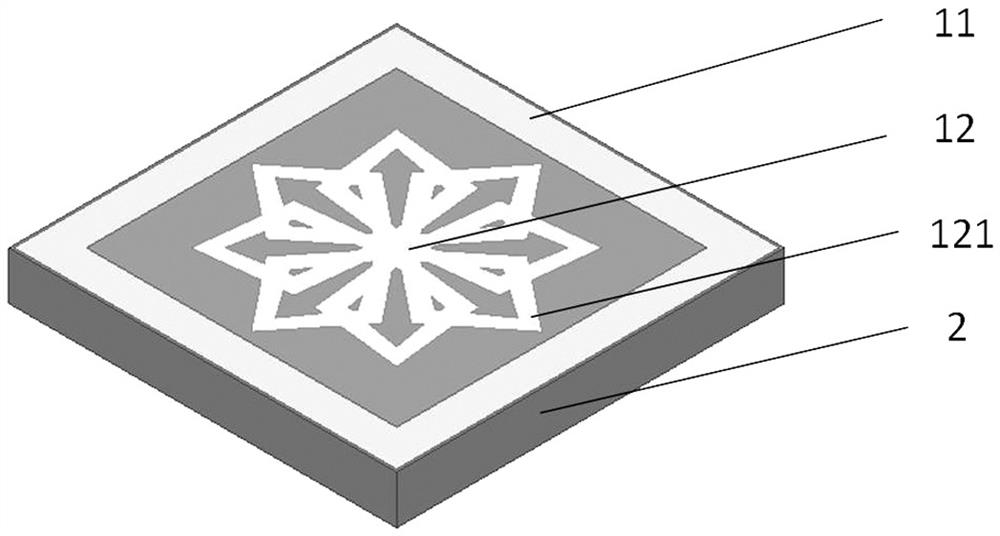
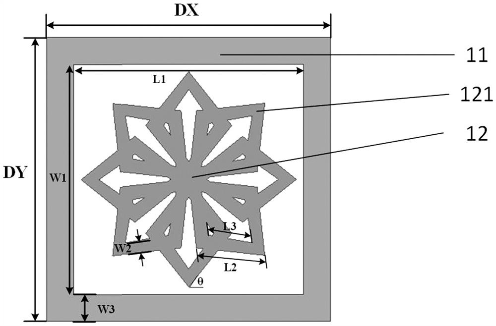
The invention discloses a high-resonance-ratio double-stop-band frequency selective surface structure and unit structure, which belong to the technical field of electromagnetic waves and are characterized by comprising a metal layer and a dielectric substrate, the metal layer is provided with a square annular patch and a diamond ring combined patch; the center of the diamond ring combined patch coincides with the center of the metal layer; the rhombic ring combined patch is formed by sequentially rotating rhombic ring-shaped patches around the center of the structure by 45 degrees and combining the rhombic ring-shaped patches; and the square ring-shaped patch is arranged around the periphery of the rhombic ring combined patch. The structure is small in size, and the requirement for miniaturization of the device can be met; the polarization stability is very good, the resonant frequency deviation belongs to an acceptable range when TE and TM polarized incident waves irradiate, and the characteristic of high resonance ratio is always achieved; and meanwhile, the antenna has very good angle stability, and in TE and TM modes, when incident waves are irradiated at different angles, the first resonant frequency deviation always has a high resonance ratio characteristic within an acceptable range.

Description

technical field [0001] The invention belongs to the field of electromagnetic wave technology, and in particular relates to a high resonance ratio double stopband frequency selection surface structure and a unit structure. Background technique [0002] Frequency Selective Surface (FSS) is a passive two-dimensional array periodic structure, which has a selective effect on electromagnetic waves. Based on its structural design, it can reflect or transmit electromagnetic waves of specific frequencies. The general frequency selective surface structure can be divided into patch type and slot type. The patch type exhibits band-stop characteristics, and the slot type exhibits band-pass characteristics. Based on the unique filtering properties of frequency-selective surfaces, it has become a research hotspot and has been widely used in antennas, metamaterials, microwave device design and other fields. [0003] The disadvantage of the existing frequency selection surface is that it ha...

Claims


Application Information

Patent Timeline
IPC IPC(8): H01Q15/00
CPCH01Q15/0013
Inventor 李毅
Owner 西安旭彤电子科技股份有限公司
Learn More