
Liquid ammonia phase change cooling type hybrid power thermal management system

A heat management system, phase change cooling technology, applied in the direction of charging system, engine components, combustion engine, etc., can solve the problems of low volume efficiency of ammonia fuel engine, low thermal efficiency, low energy utilization rate, poor combustion effect, etc., to increase the system Reliability, precise injection timing, and the effect of preventing cavitation

Active Publication Date: 2022-03-08
HARBIN ENG UNIV
View PDF7 Cites 1 Cited by
  • Summary
  • Abstract
  • Description
  • Claims
  • Application Information

AI Technical Summary

Problems solved by technology

At the same time, it is worth noting that although from the perspective of engine combustion emissions, new alternative fuels have great potential for emission reduction, but from the perspective of the entire life cycle of fuels, existing alternative fuels need to solve energy green regeneration, which drives the development of the entire energy industry chain. change
At present, there is no mature ammonia fuel power plant in the world. The ammonia fuel engine improved by diesel engine has problems such as low volume efficiency, poor combustion effect, low thermal efficiency and energy utilization rate, which limit its popularization and application.

Method used


Image

  • Liquid ammonia phase change cooling type hybrid power thermal management system
  • Liquid ammonia phase change cooling type hybrid power thermal management system
  • Liquid ammonia phase change cooling type hybrid power thermal management system

Examples


Embodiment Construction

[0048] The present invention is described in more detail below in conjunction with accompanying drawing example:

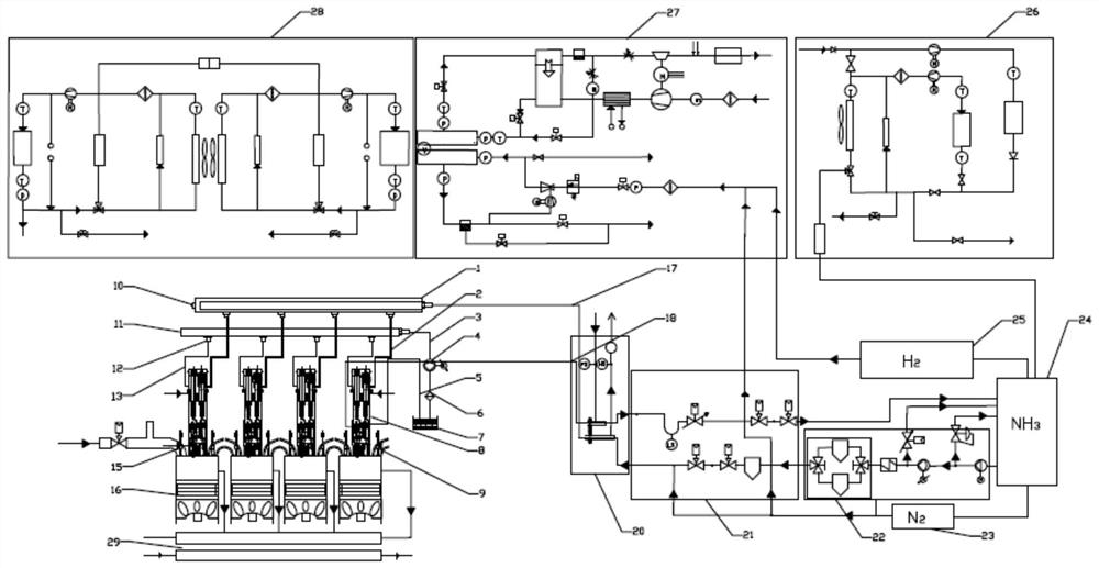
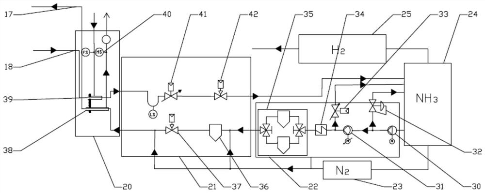
[0049] combine Figure 1-17 , figure 1 It is a schematic diagram of the overall structure of the present invention, a liquid ammonia phase-change cooling hybrid thermal management system, including: a fuel supply system, a liquid ammonia and hydrogen supply system, a liquid ammonia-diesel dual-fuel cylinder 16, and a liquid ammonia-diesel dual-fuel injector 8 , a hydrogen fuel cell supply system 27 , a cooling system 28 , a double-action heat pump 26 and a waste heat utilization system 29 . The fuel supply system consists of a fuel tank 7, a filter 6, a high-pressure fuel pump and a motor 4, a fuel common rail pipe 11, a flow limiter 12, high-pressure fuel pipes 3 and 13, and an injector 8. , The filter 6 communicates with the oil tank 7, and the flow limiter 12 communicates with the injector 14 through the high pressure oil pipe 13.

[0050] figure 2 It is a...


PUM


Abstract

The invention aims to provide a liquid ammonia phase change cooling type hybrid power thermal management system which comprises an ejector, a liquid ammonia hydrogen supply system, a liquid ammonia common rail pipe, a fuel oil common rail pipe and an oil tank, and the liquid ammonia hydrogen supply system comprises a liquid ammonia storage tank, an ammonia pumping system, a flow dividing system and an ammonia inlet and outlet system. The fuel oil common rail pipe is connected with the oil tank and a one-way oil inlet of the ejector, the liquid ammonia common rail pipe is connected with the ammonia inlet and outlet system and a one-way ammonia inlet of the ejector, an ammonia inlet pipe and an ammonia return pipe are arranged in the ammonia inlet and outlet system, and the ammonia pumping system comprises a liquid ammonia storage flow divider, a low-pressure pump and a high-pressure pump. The flow dividing system comprises a storage tank, an ammonia inlet control valve, a safety valve and an ammonia outlet control valve. The cold start problem of the engine under the cold condition can be effectively solved, the power consumption of the compressor is reduced, waste heat utilization is achieved, and the energy utilization rate is increased. Meanwhile, a feasible ammonia fuel application path is provided, and three purposes of one ammonia fuel are achieved.

Description

technical field [0001] The invention relates to an engine, specifically a hybrid engine. Background technique [0002] Under the background of green and low-carbon ships, the development of ships has entered a critical period of transformation and upgrading. In the future, ships require high flexibility in power. Power flexibility includes flexible configuration of power devices, fuel supply, flexibility of injection systems and fuel storage. , transfer, filling flexibility. Power diversity and fuel diversity will be an inevitable trend in the development of ships. Therefore, the research and development of marine low-carbon clean fuel supply and injection systems is to meet the current and future technological development needs and improve technological innovation, product competitiveness and corporate influence. key measures. Ammonia is one of the typical low-carbon fuels. Compared with hydrogen fuel, it has higher energy storage, is easier to store and transport, and ha...

Claims


Application Information

Patent Timeline
IPC IPC(8): F02M43/04F02M55/02F02M55/04F02M61/10
CPCF02M43/04F02M55/025F02M55/04F02M61/10Y02T10/12Y02T10/30F01P3/02F02M43/00F02M51/0653F02M2200/44F02M57/025F02M63/0035F02M2200/315F02M2200/40F02D19/0644F02D19/10F02D19/0694F02D19/0684H01M2250/407F02B65/00F25B30/00H01M8/00F02B2201/062F01P2003/001F01P2003/021
Inventor 范立云魏云鹏毛运涛许菁吴岳霖张瀚文
Owner HARBIN ENG UNIV
Learn More