
Oxygen lance nozzle and blowing smelting method thereof

A technology of an oxygen lance nozzle and a smelting method, applied in the direction of manufacturing converters, etc., can solve the problems of affecting the iron yield, low dephosphorization efficiency of molten steel, and high residual iron content

Pending Publication Date: 2022-03-04
SHOUGANG CORPORATION
View PDF5 Cites 0 Cited by
  • Summary
  • Abstract
  • Description
  • Claims
  • Application Information

AI Technical Summary

Problems solved by technology

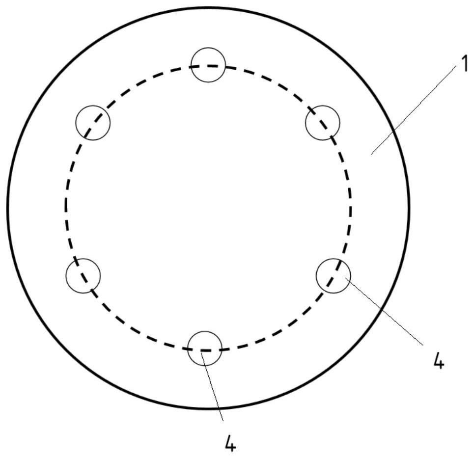
At present, most of the nozzles have six holes, and the six holes of the nozzle are all Laval structures, which are distributed on the end face of the nozzle at equal angles and distances. Using this structure of nozzles to spray oxygen for smelting, the dephosphorization efficiency of molten steel Low, and the residual iron content in the slag is high, which affects the yield of iron

Method used


Image

  • Oxygen lance nozzle and blowing smelting method thereof
  • Oxygen lance nozzle and blowing smelting method thereof

Examples


Embodiment 1

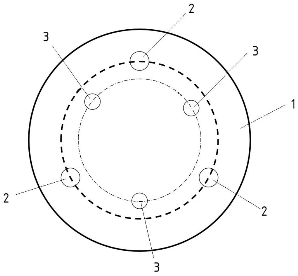
[0052] Embodiment 1 provides an oxygen lance nozzle, which is provided with 3 large holes and 3 small holes, the throat diameter of the large holes is 45.3mm, the central inclination angle is 15.5°, the Mach number is 2.05, and the distribution circle diameter is 0.56 D, the large hole corresponds to the jet flow outward, and the jet O 2 ; The throat diameter of the small hole is 36.6mm, the center inclination angle is 11.5°, the Mach number is 2.15, the diameter of the distribution circle is 0.52D, the small hole corresponds to the jet flow inward, and the CO injection 2 +O 2 Mixed gas, among them, CO 2 The volume fraction of oxygen is 10%, and the volume fraction of oxygen is 90%.

[0053] The oxygen lance nozzle is used to spray and smelt the molten iron in the converter. The capacity of the converter is 300t, the loading capacity of molten iron is 275t, the loading capacity of scrap steel is 60t, the total flow rate of the three large holes is 40000Nm3 / h, and the three s...

Embodiment 2

[0055] Embodiment 2 takes embodiment 1 as a reference, and the difference between embodiment 2 and embodiment 1 is that the volume fraction of carbon monoxide is 20% in embodiment 2, and the flow rate of the mixed gas injected by the large hole is 38000Nm 3 / h, the flow rate of the mixed gas injected by the small hole is 220000Nm 3 / h.

Embodiment 3

[0057] Embodiment 3 is with reference to embodiment 1, and embodiment 3 is different from embodiment 1, and the central inclination angle of large hole is 14 ° in embodiment 3, and the central inclination angle of small hole is 10.5 °, and the throat diameter of large hole is 42mm, the throat diameter of the small hole is 33mm, and the volume fraction of carbon monoxide in the mixed gas injected from the small hole is 30%.


PUM

PropertyMeasurementUnit
diameteraaaaaaaaaa
diameteraaaaaaaaaa
diameteraaaaaaaaaa

Abstract

The invention discloses an oxygen lance nozzle and a blowing smelting method thereof, belongs to the technical field of converter oxygen lance nozzles, is used for converter top-blowing smelting, and is provided with a large hole and a small hole which are both of a Laval structure; the small hole of each spray head is formed in a circle defined by the large holes of the spray heads, and the included angle between the central axis of each large hole of each spray head and the central axis of each spray head is larger than that between the central axis of each small hole of each spray head and the central axis of each spray head; wherein a large hole of the spray head is used for blowing oxygen into the converter; and the small hole of the nozzle is used for blowing mixed gas of oxygen and carbon dioxide into the converter. The oxygen lance nozzle provided by the invention is used for blowing and smelting molten iron, the carbon-oxygen product is 0.0014-0.0016, and the carbon-oxygen product is low; the content of T.Fe in the slag is 14-18%, and the yield of molten steel iron is high; the dephosphorization rate of the molten steel is 89-92%, and the dephosphorization effect is good; the average volume fraction of CO in the coal gas is 53-55%, and carbon dioxide is efficiently utilized.

Description

technical field [0001] The invention belongs to the technical field of converter oxygen lance nozzles, and in particular relates to an oxygen lance nozzle and a blowing smelting method thereof. Background technique [0002] The oxygen lance is a structure that provides oxygen for converter smelting. There is a nozzle at the bottom of the oxygen lance, and oxygen is sprayed from the nozzle into the converter for molten iron smelting. At present, most of the nozzles have six holes, and the six holes of the nozzle are all Laval structures, which are distributed on the end face of the nozzle at equal angles and distances. Using this structure of nozzles to spray oxygen for smelting, the dephosphorization efficiency of molten steel Low, and the residual iron content in the slag is high, which affects the yield of iron. Contents of the invention [0003] In order to solve the above-mentioned technical problems, the present invention provides an oxygen lance nozzle and its injec...

Claims


Application Information

Patent Timeline
Patent Type & Authority Applications(China)
IPC IPC(8): C21C5/46C21C7/064C21C5/32
CPCC21C5/4606C21C7/064C21C5/32
Inventor 邵肖静董文亮李海波朱国森关顺宽季晨曦陈斌丁国慧吉立鹏郭小龙王延飞赵长亮朱志远
Owner SHOUGANG CORPORATION
Learn More