Low-absorption and low-emission thermal control coating with solar absorption ratio changing along with incident angle and preparation method of low-absorption and low-emission thermal control coating

A solar absorption ratio and thermal control coating technology, which is applied in the direction of radiation-absorbing coatings, coatings, metal-free paints, etc., can solve the problem of reduced heat flow input, lower temperature, and affecting the high-precision thermal control performance of the spacecraft surface and structural precision

Active Publication Date: 2022-03-04
BEIJING SATELLITE MFG FACTORY
View PDF4 Cites 0 Cited by
  • Summary
  • Abstract
  • Description
  • Claims
  • Application Information

AI Technical Summary

Problems solved by technology

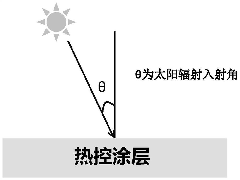
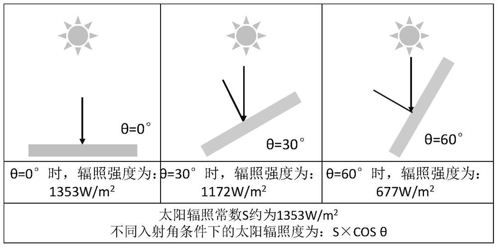
[0004] In order to overcome the deficiencies in the prior art, the inventor has carried out intensive research and provided a low-absorption and low-emission thermal control system whose solar absorption ratio changes with the incident angle The coating and its preparation method, the coating has different solar absorption ratios under different solar incidence angles, especially the absorptivity significantly increases under the conditions of large incidence angles, which solves the problem of conventional coatings with relatively large oblique incidence angles of the sun. When the heat flow input decreases sharply when it is large, the temperature drops or a large temperature gradient is formed with the high-temperature part, which in turn affects the high-precision thermal control performance and structural accuracy of the spacecraft surface.

Method used


Image

  • Low-absorption and low-emission thermal control coating with solar absorption ratio changing along with incident angle and preparation method of low-absorption and low-emission thermal control coating
  • Low-absorption and low-emission thermal control coating with solar absorption ratio changing along with incident angle and preparation method of low-absorption and low-emission thermal control coating
  • Low-absorption and low-emission thermal control coating with solar absorption ratio changing along with incident angle and preparation method of low-absorption and low-emission thermal control coating

Examples


preparation example Construction

[0038] According to a second aspect of the present invention, there is provided a method for preparing a low-absorption and low-emission thermal control coating whose solar absorption ratio varies with the incident angle, comprising the following steps:

[0039] Weigh the filler, organic solvent and surfactant in proportion and mix them, then stir for 2-3 hours at 60-100°C;

[0040] Add the binder in proportion to the above mixing system, and then stir evenly at room temperature;

[0041] Add curing agent and catalyst in proportion to the above system, and stir evenly to form a coating paint that can be used for spraying;

[0042] The paint is directly coated on the surface of the product or part to be sprayed by air spraying, and the coating thickness is not less than 25 μm.

Embodiment 1

[0045] (1) Weigh 130g of flake metal aluminum powder and put it into a three-necked flask (particle size is about 35μm, thickness is not more than 2μm), then add 250g of mixed solvent of xylene and butyl acetate (mass ratio is 1:1), and then add Silane coupling agent KH550 2g, boric acid 0.02g; Stir for 3 hours at 80°C;

[0046] (2) Add 100 g of methylol silicone resin (molecular weight: 8,000 to 10,000) into the above system, and stir for 2 hours at room temperature;

[0047] (3) Add 5g ethyl orthosilicate and 2g dibutyltin dilaurate to the above system to obtain the paint material;

[0048] (4) Adopt the method of air spraying, spray on the surface of the parts, and the thickness of the coating after drying is 45-55 μm.

[0049] After testing, the hemispherical emissivity of the coating is 0.16, and the solar absorption ratio, solar radiation constant and thermal radiation absorption capacity per unit area under different incident angle conditions are as follows figure 2 ...

Embodiment 2

[0054] (1) Weigh 160g of flake metal aluminum powder and put it into a three-necked flask (particle size is about 45μm, thickness is not more than 2μm), then add 500g of mixed solvent of xylene and butyl acetate (mass ratio is 2:1), and then add KH550 silane coupling agent 3g, boric acid 0.1g; Stir at 100°C for 2 hours;

[0055] (2) Add 100 g of methylol silicone resin (molecular weight: 2000 to 5000) into the above system, and stir for 3 hours at room temperature;

[0056] (3) Add 4g ethyl orthosilicate and 3g dibutyltin dilaurate to above-mentioned system, obtain paint material;

[0057] (4) Adopt the method of air spraying, spray on the surface of the parts, and the thickness of the coating after drying is 35-47 μm.

[0058] After testing, the hemispherical emissivity of the coating is 0.15, and the solar absorption ratio, solar radiation constant and thermal radiation absorption capacity per unit area under different incident angles are shown in Table 2 below:

[0059] T...


PUM

PropertyMeasurementUnit
thicknessaaaaaaaaaa
particle sizeaaaaaaaaaa
thicknessaaaaaaaaaa

Abstract

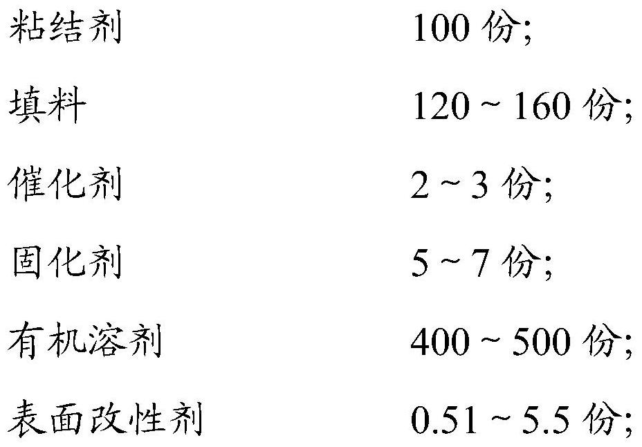
The invention provides a low-absorption and low-emission thermal control coating with a solar absorption ratio changing along with an incident angle and a preparation method of the low-absorption and low-emission thermal control coating. The low-absorption and low-emission thermal control coating comprises the following components in parts by mass: 100 parts of a binder; 120 to 160 parts of filler; 2-3 parts of a catalyst; 5-7 parts of a curing agent; 400 to 500 parts of an organic solvent; 0.51 to 5.5 parts of a surface modifier; wherein the adhesive is hydroxymethyl organic silicon resin, and the molecular weight of the adhesive is 2000 to 10000; the surface modifier is boric acid and a KH550 silane coupling agent; the coating is implemented by adopting an air spraying method, and the thickness is not less than 25 microns. The coating has different solar absorptivity under different solar incident angle conditions, and particularly, the absorptivity under a large incident angle condition is remarkably increased, so that the problem that the temperature is reduced or a large temperature gradient is formed between the coating and a high-temperature part due to the fact that heat flow input of a conventional coating is sharply reduced when the solar oblique incident angle is large is solved. And the high-precision thermal control performance and the structural precision of the surface of the spacecraft are influenced.

Description

technical field [0001] The invention belongs to the technical field of thermal control coatings for spacecraft, in particular to a low-absorption and low-emission thermal control coating whose solar absorption ratio changes with incident angles and a preparation method thereof. Different solar absorption ratios. Background technique [0002] Under space environmental conditions, the thermal control coating on the surface of the spacecraft controls the heat flow into and out of the spacecraft and maintains the surface and internal temperature of the spacecraft. The solar absorption ratio is the ability of the coating to absorb solar heat radiation, and the hemispherical emissivity reflects the ability of the coating to radiate heat to the deep cold space. Affected by the high-vacuum environment, when the spacecraft is working in orbit, the coating will absorb solar radiation and cause the temperature of the spacecraft to rise, and the radiation heat leakage of the coating to...

Claims


Application Information

Patent Timeline
Patent Type & Authority Applications(China)
IPC IPC(8): C09D183/06C09D5/32C09D5/38
CPCC09D183/06C09D5/32C09D5/38C08K2003/0812C08K7/00C08K3/08C08K9/06C08K9/02
Inventor 庞健张家强平托白晶莹崔庆新张立功王兵存孙浩然李海霞
Owner BEIJING SATELLITE MFG FACTORY
Why Eureka
Try Eureka