A kind of finishing process of stator and rotor for automobile engine

A technology of automobile engines and stators and rotors, which is applied in the direction of manufacturing tools and other manufacturing equipment/tools. It can solve the problems of inconvenient and quick replacement, affecting the processing efficiency of engine stators and rotors, and affecting the normal operation of the transmission structure on the machine tool, so as to ensure the finishing. efficiency effect

Active Publication Date: 2022-07-29
扬州恒众精密机械有限公司
View PDF2 Cites 0 Cited by
  • Summary
  • Abstract
  • Description
  • Claims
  • Application Information

AI Technical Summary

Problems solved by technology

[0003] When the stator and rotor of the current engine are finished on the machine tool, the next set of stator and rotor can be finished only after one set of stator and rotor is finished, which greatly affects the device’s ability to adjust the engine’s stator and rotor. Processing efficiency; and in the process of finishing the stator and rotor of the current automobile engine, the metal debris generated will often cover the processing machine tool. These debris will not only fall into some corners of the machine tool that are difficult to clean, but also affect the The normal operation of the transmission structure on the machine tool; at the same time, during the finishing process of the stator and rotor of the current automobile engine, a large amount of metal dust is often generated, which will also greatly increase the wear of the rotating parts of the machine tool, and in the finishing process of the stator and rotor Finally, due to grinding and turning, the stator and rotor will generate a lot of heat, which is not convenient for quick replacement of the stator and rotor after processing

Method used


Image

  • A kind of finishing process of stator and rotor for automobile engine
  • A kind of finishing process of stator and rotor for automobile engine
  • A kind of finishing process of stator and rotor for automobile engine

Examples


Embodiment 1

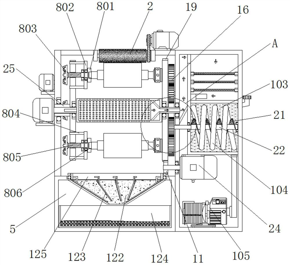
[0053] Example 1, as Figure 2-4 As shown in the figure, before finishing the stator and rotor, the operator passes his hand through the square through hole and then rotates a set of handwheels 803 close to the door of the processing chamber 1 counterclockwise, and uses the thread action to force the threaded rod 805 to move closer to the first servo motor. One end of 6 moves, driving the rotating plate 801 to approach the first servo motor 6 together, and the distance between the rotating plate 801 and the rotating holder 9 increases, and then the operator manually inserts one end of the stator and rotor into the recess of the rotating holder 9. slot, and turn the hand wheel 803 clockwise, so that the other end of the stator and rotor is clamped into the slot 806, so as to install the stator and rotor, so as to facilitate the subsequent finishing of the stator and rotor, and replace the finished stator and rotor. At this time, turn the handwheel 803 clockwise to drive the thr...

Embodiment 2

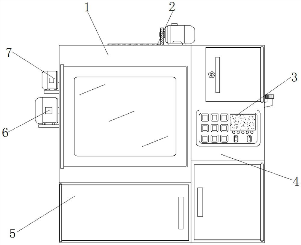
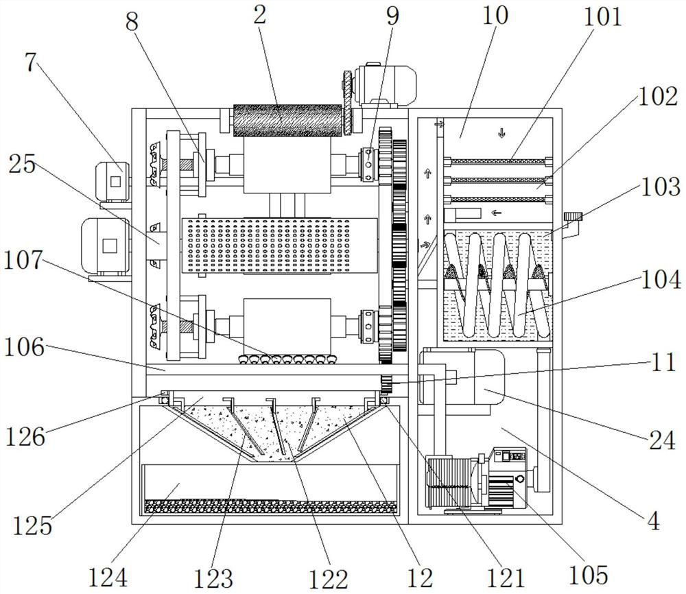
[0054] Example 2, as Figure 1-10 As shown in the figure, when finishing the stator and rotor, the device first controls the second servo motor 24 to rotate clockwise through the control panel 3, and uses the transmission of the driving gear 11 and the second ring rack 19 to drive the two sets of turntables 13 to reverse each time. The clockwise is rotated 90°, so that the stator and rotor pass through the bottom of the grinding device 2 in turn, and then pass through one side of the turning assembly 7 and the top of the rotating ring 125, and when the turntable 13 stops, the first servo motor 6 drives the rotating chamber. 14 rotates, and the rotating bin 14 drives the three sets of rotating chucks 9 to rotate synchronously through the driving gear 18 on the first rotating tube 17 and the three sets of transmission gears 23, thereby driving the three sets of stators and rotors to rotate synchronously. The grinding device 2 is used to align the stator and rotor Grinding is per...

Embodiment 3

[0055] Example 3, as Figure 2-6 As shown in and 9-10, when dusting the inside of the processing bin 1, the air suction pump 105 is controlled by the control panel 3 to inhale, and the metal dust generated by the grinding device 2 is mixed with the air and enters the rotating bin 14 through the air inlet 15. After that, the metal dust and air enter the interior of the filter chamber 102 through the first rotating pipe 17, and the metal dust will be filtered and blocked by the three sets of filter screens 101, and the filtered air will pass through the heat exchange pipe 104. The air pump 105 is transported to the inside of the air pipe 106, and the filtered air is finally sprayed out through the nozzle 107 to blow and cool the surface of the bottom group of stators and rotors, so that the processed stators and rotors can be quickly replaced, and the nozzles 107 spray out The surface of the set of stators and rotors will also be blown and dusted, and the blown dust will also be...


PUM


Abstract

The invention discloses a finishing process for a stator and rotor for an automobile engine, comprising the following steps: 1. First, cutting a raw material silicon steel sheet into strips, then punching a stator sheet and a rotor sheet including punched grooves by a punch, and then aligning the stator The sheet and the rotor sheet are rolled with insulating varnish, and then the stator sheet and the rotor sheet are laminated to form the stator rotor; 2. Then the stator is pressed into the casing to form the finished stator, and then the rotor is passed through the shaft and the rotor shaft is processed to form the finished rotor. The invention controls the second servo motor to rotate clockwise, uses the driving gear and the second ring rack to drive the two groups of turntables to rotate 90 degrees counterclockwise each time, and the rotating bin cooperates with the three groups of transmissions through the driving gear on the first rotating tube The gears drive the three groups of stators and rotors to rotate synchronously. The grinding device is used to grind the stators and rotors, and the turning components are used to cooperate with the rotating stators and rotors to turn the stators and rotors. A set of stators and rotors are replaced.

Description

technical field [0001] The invention relates to the technical field of automobile engine processing, in particular to a finishing process of a stator and rotor for an automobile engine. Background technique [0002] The fixed part of the motor is called the stator, on which is installed the stationary main poles of the paired DC excitation; and the rotating part (rotor-rotor) is called the armature core, on which the armature winding is installed. It generates induced electromotive force, acts as a rotating magnetic field, and then generates electromagnetic torque for energy conversion. It is distinguished by the shape of the stator winding and the way of embedding. The stator winding can be divided into centralized and distributed according to the shape of the coil and the way of embedded wiring. two types. [0003] When the stator and rotor of the current engine are finished on the machine tool, it is often after a group of stator and rotor is finished that they can be re...

Claims


Application Information

Patent Timeline
Patent Type & Authority Patents(China)
IPC IPC(8): B23P15/00B23P23/04
CPCB23P15/00B23P23/04
Inventor 徐贞林顾文娥
Owner 扬州恒众精密机械有限公司
Why Eureka
Try Eureka