Vapor chamber with gradient wick structure and preparation method thereof

A technology of liquid-absorbing core and soaking plate, which is applied in lighting and heating equipment, indirect heat exchangers, modification by using liquid cooling, etc., can solve the problem of liquid-absorbing core with large capillary driving force and high permeability It can further improve the performance of the vapor chamber, reduce the overall performance of the vapor chamber, etc., and achieve the effects of enhancing heat transfer performance and working stability, improving hydrophobic characteristics, and improving hydrophilic characteristics

Pending Publication Date: 2022-02-08
INST OF ENGINEERING THERMOPHYSICS - CHINESE ACAD OF SCI +1
View PDF0 Cites 4 Cited by
  • Summary
  • Abstract
  • Description
  • Claims
  • Application Information

AI Technical Summary

Problems solved by technology

[0007] (1) With the urgent need for compactness and high performance of the vapor chamber, it is difficult for the traditional single-structure liquid-absorbing core to have both the characteristics of large capillary driving force and high permeability, resulting in a decrease in the overall performance of the vapor chamber;
[0008] (2) At present, most of the vapor chambers use sintered liquid-absorbing cores, but the surface modification of the liquid-absorbing cores is rarely carried out, which fails to further improve the performance of the vapor chamber;
[0009] (3) In the face of high heat flux density conditions, the vapor chamber may dry out due to the failure of the liquid working fluid to quickly return to the evaporation area, resulting in a decrease in the heat transfer capacity of the vapor chamber

Method used


Image

  • Vapor chamber with gradient wick structure and preparation method thereof
  • Vapor chamber with gradient wick structure and preparation method thereof
  • Vapor chamber with gradient wick structure and preparation method thereof

Examples


Embodiment 1

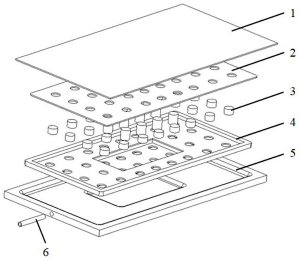
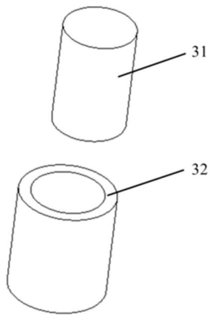
[0084] Such as figure 1 As shown, the vapor chamber of this embodiment includes: an upper shell plate 1 , a liquid-absorbing core 2 at the condensation end, a support column 3 , a liquid-absorbing core 4 at the evaporation end, a lower shell plate 5 and a liquid injection pipe 6 .

[0085] The thicknesses of the upper shell plate and the lower shell plate are 0.5 mm and 1.5 mm respectively.

[0086] The lower shell plate is stepped, and the protruding part is the area of ​​the tooling surface where the heat source contacts.

[0087] The lower shell plate leaves a liquid injection port for placing a liquid injection pipe.

[0088] The upper shell plate and the lower shell plate are respectively sintered with a condensing end liquid-absorbing core and an evaporating end liquid-absorbing core.

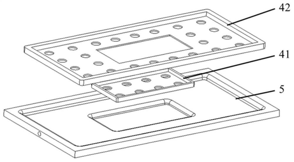
[0089] The evaporating end liquid-absorbing core includes #1 evaporating-end liquid-absorbing core 41 on the working surface area and #2 evaporating end liquid-absorbing core 42 away fr...

Embodiment 2

[0101] Such as Figure 7 As shown, the vapor chamber of this embodiment is different from that of Embodiment 1: the structural shape of the lower shell of the vapor chamber in Embodiment 2 is flat. All the other are identical with embodiment 1.


PUM


Abstract

The invention discloses a vapor chamber with a gradient wick structure and a preparation method of the vapor chamber. The vapor chamber comprises an upper shell plate, a condensation end wick, a support column, an evaporation end wick, a lower shell plate and a liquid injection pipe, wherein the inner surface of the lower shell plate can be a plane or a stepped concave surface, the inner surface of the lower shell plate can be divided into different areas according to the relative positions of the lower shell plate and a heat source contact area, the evaporation end wick is a composite porous medium with different capillary apertures and porosities, and the capillary apertures and the porosities change along with the change of the positions of the different areas. Therefore, a wick structure with gradient characteristics is formed. The effective capillary aperture, porosity and the like of the wick are regulated and controlled, the wick structure with large capillary driving force, high permeability and small flow resistance is prepared, and the vapor chamber prepared on the basis of the wick structure has the advantages of large heat transfer capacity, high heat transfer efficiency, high inverse gravity performance, high reliability and the like; and the heat dissipation requirement of electronic equipment with high heat flux density can be met.

Description

technical field [0001] The invention belongs to the technical field of heat dissipation of electronic information systems, and in particular relates to a vapor chamber with a gradient liquid-absorbing core structure and a preparation method thereof. Background technique [0002] With the continuous innovation and development of electronic information technology, electronic equipment is gradually developing in the direction of system compactness, high performance and high integration, and the power consumption and heat flux density of electronic chips are also getting higher and higher. Relevant studies have shown that the current local heat flux of electronic chips will exceed 1000 W / cm 2 , and the average heat flux has reached 500 W / cm 2 If there is no reasonable heat dissipation method to dissipate heat from the electronic chip, the temperature of the electronic chip will rise, its working stability, reliability and service life will be greatly reduced, and even thermal d...

Claims


Application Information

Patent Timeline
Patent Type & Authority Applications(China)
IPC IPC(8): H05K7/20F28D15/04
CPCH05K7/20318H05K7/20309F28D15/04F28D15/046
Inventor 周国辉周敬之周峰淮秀兰贾潇
Owner INST OF ENGINEERING THERMOPHYSICS - CHINESE ACAD OF SCI
Why Eureka
Try Eureka