A kind of automatic welding machine and welding process
An automatic welding machine and welding process technology, applied in welding equipment, welding equipment, auxiliary welding equipment, etc., can solve the problems of low welding efficiency of welding machines and inability to weld with multiple drill bits, so as to reduce welding time and improve alignment efficiency , The effect of improving welding efficiency
- Summary
- Abstract
- Description
- Claims
- Application Information
AI Technical Summary
Problems solved by technology
Method used
Image

Examples
no. 1 example
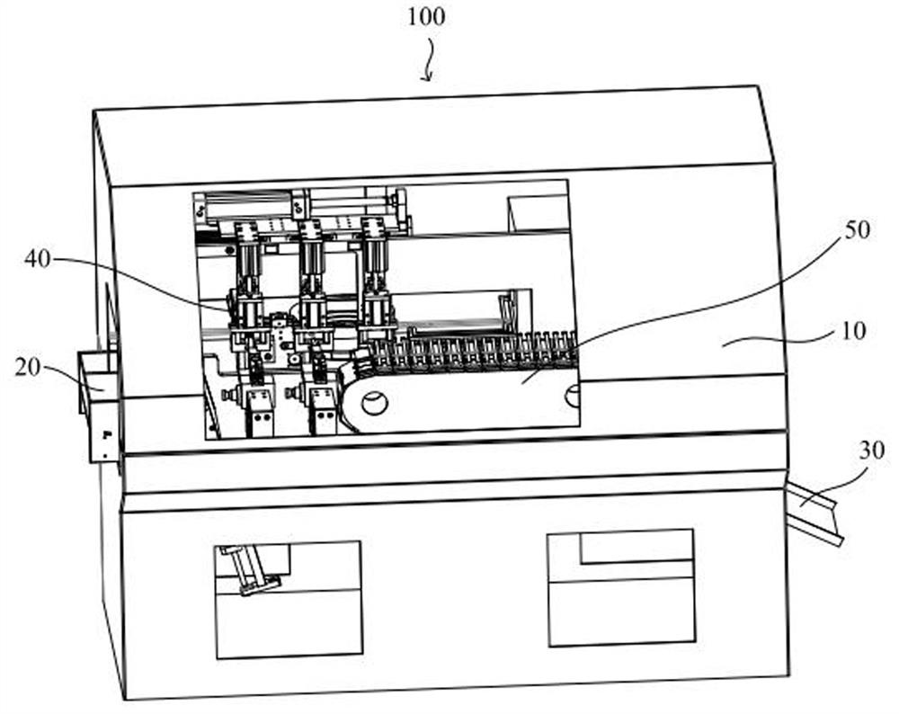
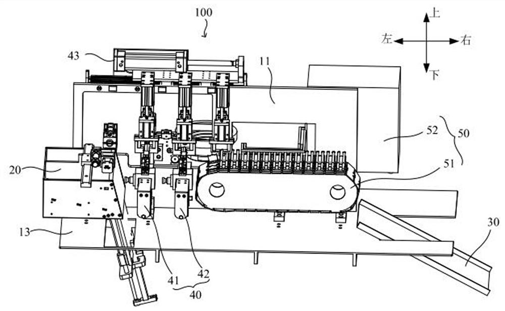
[0059] see Figure 1-Figure 2 The first embodiment of the present invention provides an automatic welding machine 100. The automatic welding machine 100 is used to realize the welding between the drill bit 61 and the alloy sheet 62, and the drill bit body 60 is formed after the drill bit 61 and the alloy sheet 62 are welded. The automatic welding machine 100 includes, for example: a casing 10 and an assembly mechanism 40 installed inside the casing 10; a feeding mechanism 20 is provided on one side of the casing 10, and a Outlet 30; wherein, the feeding mechanism 20 is used to realize the delivery of the drill bit to the assembly mechanism 40, and the assembly mechanism 40 is used to realize the assembly and welding between the drill bit 61 and the alloy sheet 62, and the final welded drill bit body 60 It is transported to the outside through the discharge port 30; it can be understood that, in order to improve the welding strength of the drill bit 61 and improve the quality o...
no. 2 example
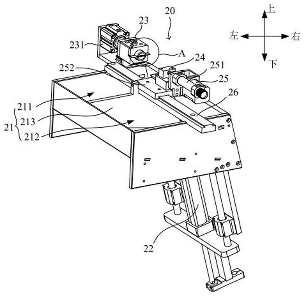
[0069] preferred, see Figure 3-Figure 10 , the second embodiment of the present invention provides a feeding mechanism 20 on the basis of the first embodiment; wherein, the feeding mechanism 20 includes: a feeding port 21, a feeding cylinder 22, a straightening part 23 and a fixing part 24 Wherein, the alignment part 23 is used to adjust the position of the drill bit 61, and the feeding cylinder 22 can deliver the drill bit 61 to the alignment part 23, and the fixing part 24 is then used to fix the drill bit 61; specifically, the alignment part 23 adjusts the drill bit 61 During the process of positioning, one end of the drill bit 61 is connected to the fixed part 24, and can rotate relative to the fixed part 24. During the rotation process, it realizes the matching connection with the alignment part 23, and then completes the alignment of the drill bit 61. ; In this embodiment, the described alignment refers to: before the drill 61 and the alloy sheet 62 are assembled, the p...
no. 3 example
[0082] The third embodiment of the present invention provides an assembly mechanism 40 on the basis of the first embodiment and the second embodiment, wherein the assembly mechanism 40 can assemble and weld the aligned drill bit 61 and the alloy sheet 62, and The assembly mechanism 40 includes: an assembly part 41, a paste dispensing part 42 and a transfer part 43; the assembly part 41 is arranged on the side of the first mounting plate 11 close to the feeding mechanism 20, and the paste dispensing part 42 is arranged on the first mounting plate 11, And between the assembly part 41 and the welding mechanism 50, the paste dispensing part 42 is provided with solder paste for realizing dispensing paste between the drill bit 61 and the alloy sheet 62; the transmission part 43 is arranged on the assembly part 41 and the dispensing paste part 42 above.
[0083] preferred, see Figure 11 and Figure 12 , the assembly part 41 is provided with a second drill bit installation position...
PUM
 Abstract
Description
Claims
Application Information
 - R&D
- Intellectual Property
- Life Sciences
- Materials
- Tech Scout
- Unparalleled Data Quality
- Higher Quality Content
- 60% Fewer Hallucinations
Browse by: Latest US Patents, China's latest patents, Technical Efficacy Thesaurus, Application Domain, Technology Topic, Popular Technical Reports.
© 2025 PatSnap. All rights reserved.Legal|Privacy policy|Modern Slavery Act Transparency Statement|Sitemap|About US| Contact US: help@patsnap.com