Overlay measurement method and manufacturing method of semiconductor device
A technology of measurement and overlay marking, which is applied in semiconductor devices, semiconductor/solid-state device parts, electric solid-state devices, etc., to solve the problem of overlay measurement and reduce the cost of photomasks
- Summary
- Abstract
- Description
- Claims
- Application Information
AI Technical Summary
Problems solved by technology
Method used
Image
Examples
Embodiment 1
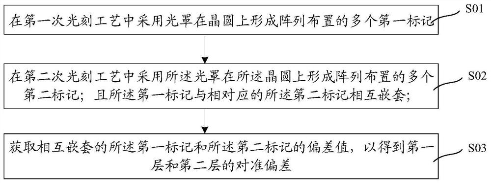
[0051] The present embodiment provides an overlay measurement method and a manufacturing method of a semiconductor device. image 3 It is a flow chart of an overlay measuring method provided in this embodiment. like image 3 As shown, the overlay measurement method provided in this embodiment includes:
[0052] S01: using a photomask to form a plurality of first marks arranged in an array on the wafer in the first layer photolithography process;
[0053] S02: Using the photomask to form a plurality of second marks arranged in an array on the wafer in the second layer photolithography process; and the first marks and the corresponding second marks are nested;
[0054] S03: Obtain the deviation value of the first mark and the second mark nested with each other, so as to obtain the alignment deviation of the first layer and the second layer.
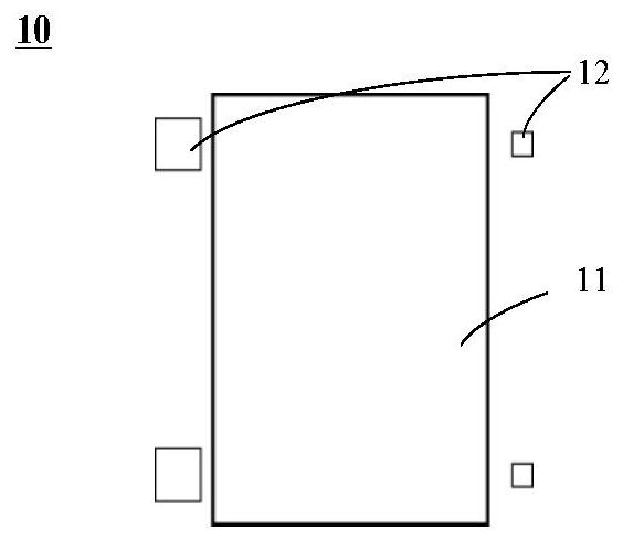
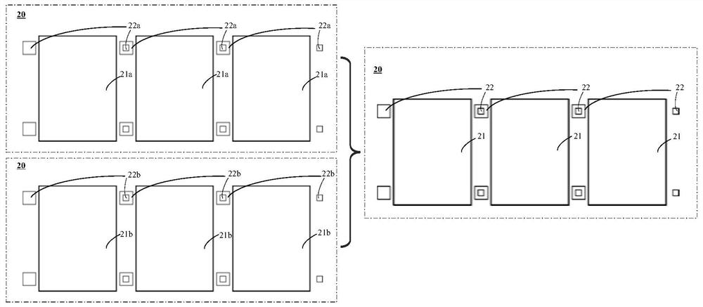
[0055] Figure 4 , Figure 5A and Figure 5B Schematic diagram of the structure of the photomask used in the overlay measurement met...
Embodiment 2
[0069] This embodiment provides an overlay measurement method. The difference from Embodiment 1 is that the first overlay mark and the second overlay mark on the mask in this embodiment are arranged symmetrically up and down with respect to the unit array pattern. In the two adjacent cell arrays formed on the wafer, the first mark on the first layer and the second mark on the second layer are nested one above the other.
[0070] Figure 9 Schematic diagram of the structure of the photomask used in the overlay measurement method provided for this implementation, Figure 10 Schematic diagrams of the structure of overlay measurement marks on the wafer after the first layer photolithography process and the second layer photolithography process in the overlay measurement method provided for this implementation. Specifically, refer to Figure 9 and Figure 10 As shown, first, a photomask 100 is provided, and the photomask 100 includes a cell array pattern 110' and an overlay mark...
PUM
 Abstract
Description
Claims
Application Information
 - R&D
- Intellectual Property
- Life Sciences
- Materials
- Tech Scout
- Unparalleled Data Quality
- Higher Quality Content
- 60% Fewer Hallucinations
Browse by: Latest US Patents, China's latest patents, Technical Efficacy Thesaurus, Application Domain, Technology Topic, Popular Technical Reports.
© 2025 PatSnap. All rights reserved.Legal|Privacy policy|Modern Slavery Act Transparency Statement|Sitemap|About US| Contact US: help@patsnap.com


